Showing posts with label How to Tweak Out a 12th Car. Show all posts

Tuesday, December 20, 2005

CRC Carpet Knife 3.2R Total Tweak Guide

Total Tweak Guide for the CRC Carpet Knife 3.2R

Essential Reading and Prerequisites
In my previous posts on statically balancing the CRC Carpet Knife, setting good ride height and correctly building the Associated reactive castor front end, I was trying to lay the foundations for ending up with a totally tweak free car.

The following three articles are hence prerequisite procedures before moving on to the steps detailed below:


Please note that I only have experience of the CRC Carpet Knife 3.2R. Obviously the Associated front end is common to many cars but my total “system” assumes you have rear pivot ball and side spring type rear end.

Read these first:

http://markpayneblog.blogspot.com/2005/12/building-associated-l4-type-front-end.html

http://markpayneblog.blogspot.com/2005/12/crc-32r-chassis-setup-static-balance.html

http://markpayneblog.blogspot.com/2005/12/measuring-ride-height-on-crc-32r.html

The Coin Trick is Not Enough

Most people use the coin trick on the front tyres whereby you lift the front off the ground via the front center point and adjust rear tweak screws for a simultaneous coin drop. In fact I will end this article with the coin trick as a final tweak check BUT… the validity of the “coin trick” is dependant on other things being right first.

With the coin trick, what you are doing is setting the rear tweak screws to equate the downstops (limit of upward front suspension travel) of the front suspension. This is a factor of how accurate the front lower arms are and the ride height spacers included under them. Why would we set the tweak on the rear springs to fix a potential error in the front arms? The rear tweak should adjust the springs when the chassis is LOADED onto the springs all round, not unloaded at the front.

Don’t worry… if you don’t get this yet… we will go through the whole thing here.

Lets Start

I am assuming you have done the following checks (read the previous posts above):

A. You have a well built front end with all the slack just shimmed out of the king pins.

B. You have a fresh ground set of accurate and equal tyres on the car. The left and right tyres are exactly the same size measured with your calipers.

C. You have set the ride height to 4mm all round using the “five points” system.

Step 1

Remove the whole rear tweak bar assembly and damping tubes. We will be setting up the front end first. Load the car with a set of cells. You will notice that I tape cells into the car. I do not use the CRC “rubber band” cell retention as I believe this can tweak the car.

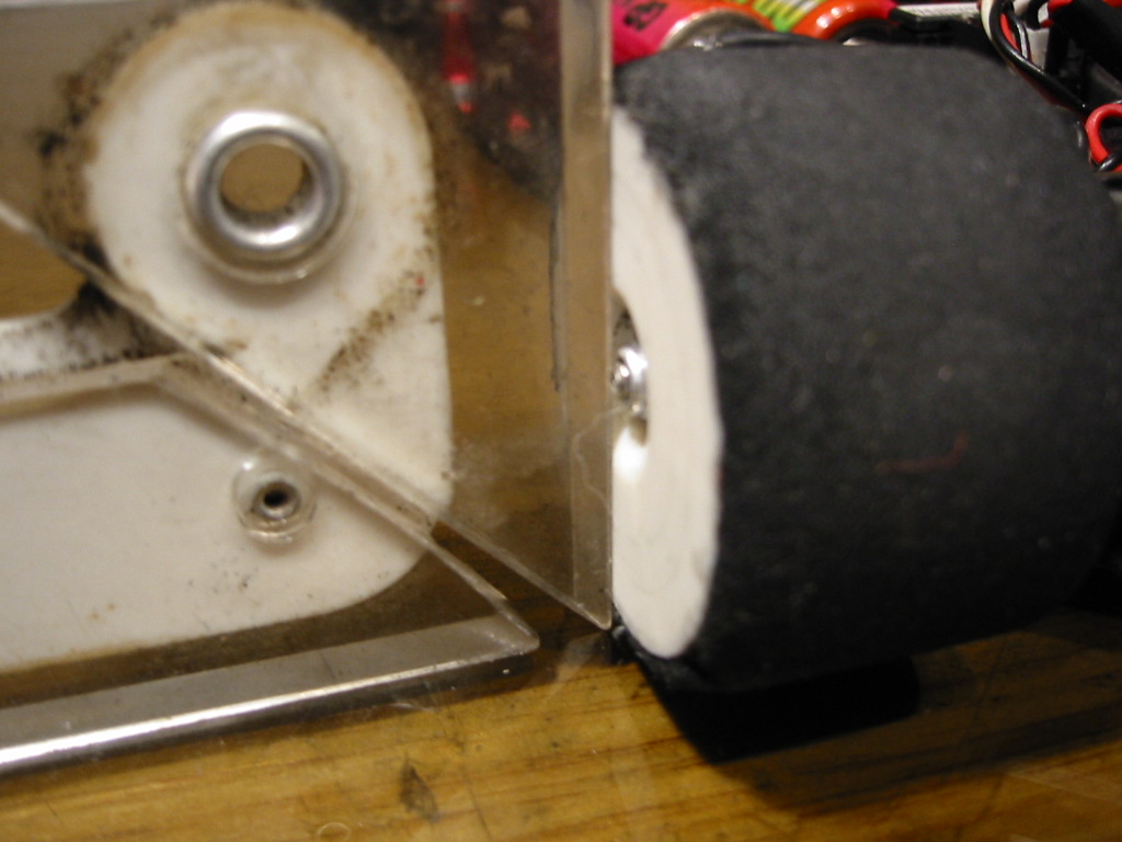
Now that the tweak bar is off, it is a good time to check the chassis pod is rotating freely. When a CRC car takes a crash, the centre pivot plate can be shifted out of line causing the rear pod action to bind. I now tend to check this every run at important meetings.

Video: Checking Pod Movement

If in doubt, loosen the two pivot plate screws and retighten them with the pod aligned with the main chassis. Recheck the pod action again.


Step 2

Spend some time and make sure the camber on the front wheels is set to 1 degree and is the same left and right. I use a protractor that I have had since my school days (its old!) but there are plenty of camber gauges on the market.


Step 3

Take the front wheels off.
I put the chassis on 5mm blocks. Hudy make these http://www.hudy.net/xhudy/products/proddesc.php?prod_id=153&kategoria=64
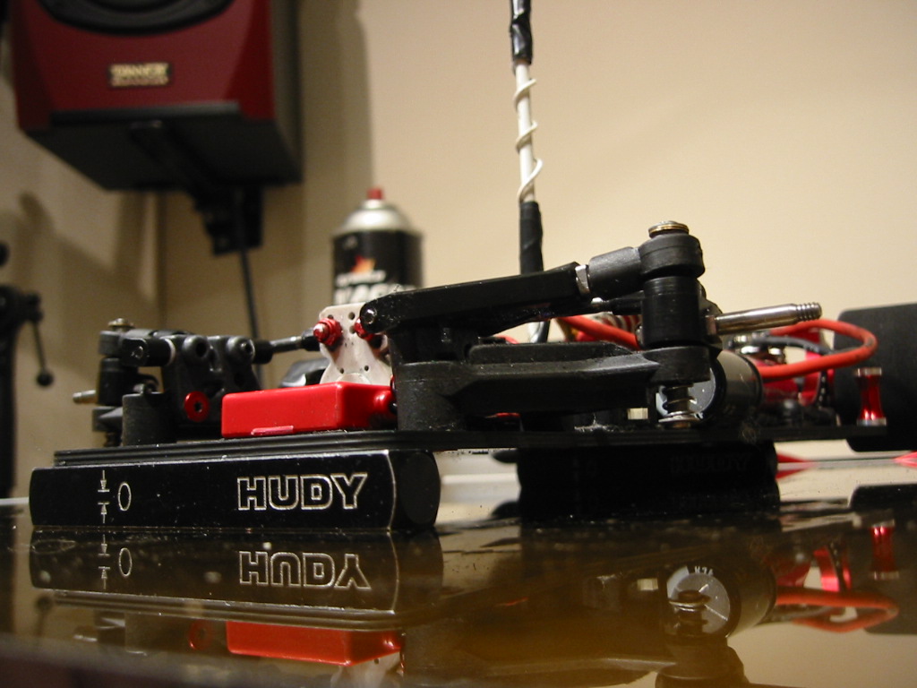

Make sure the chassis itself is on the blocks and not any protruding screw heads, cells or cell tape. If the blocks are parallel to each other there should be no “rocking” evident. If the chassis rocks on the blocks then it is twisted. You will never tweak this car out with a twisted chassis.
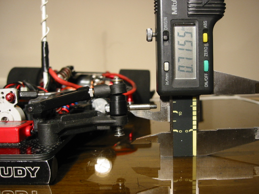
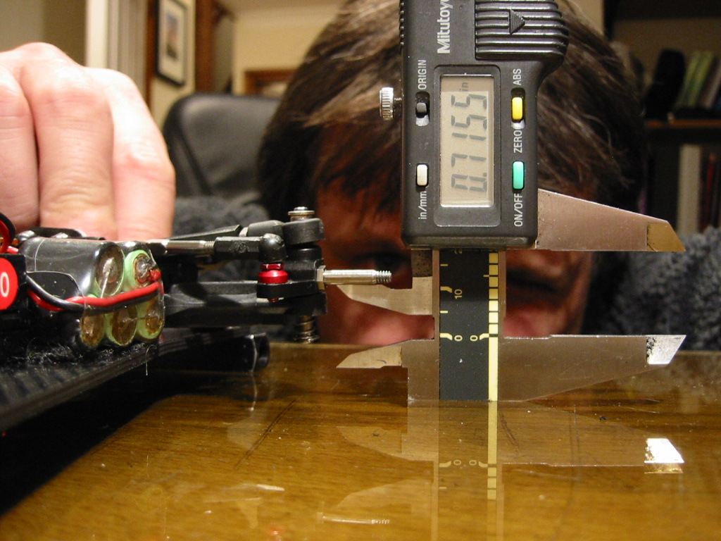


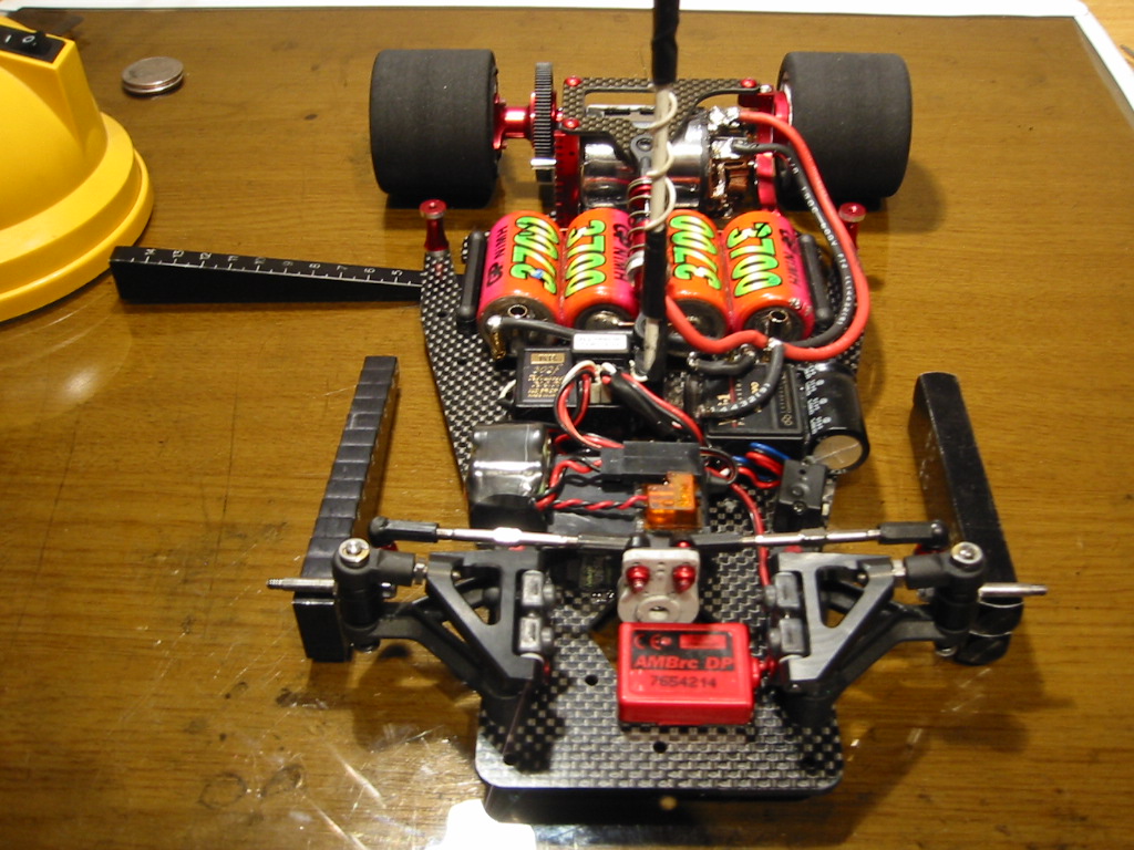
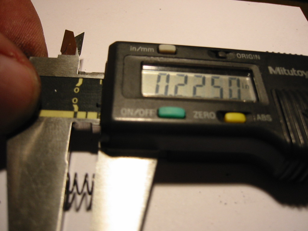
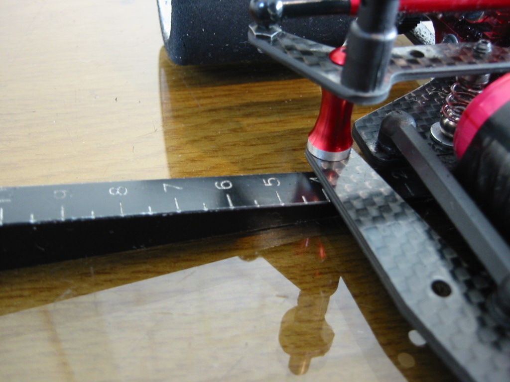
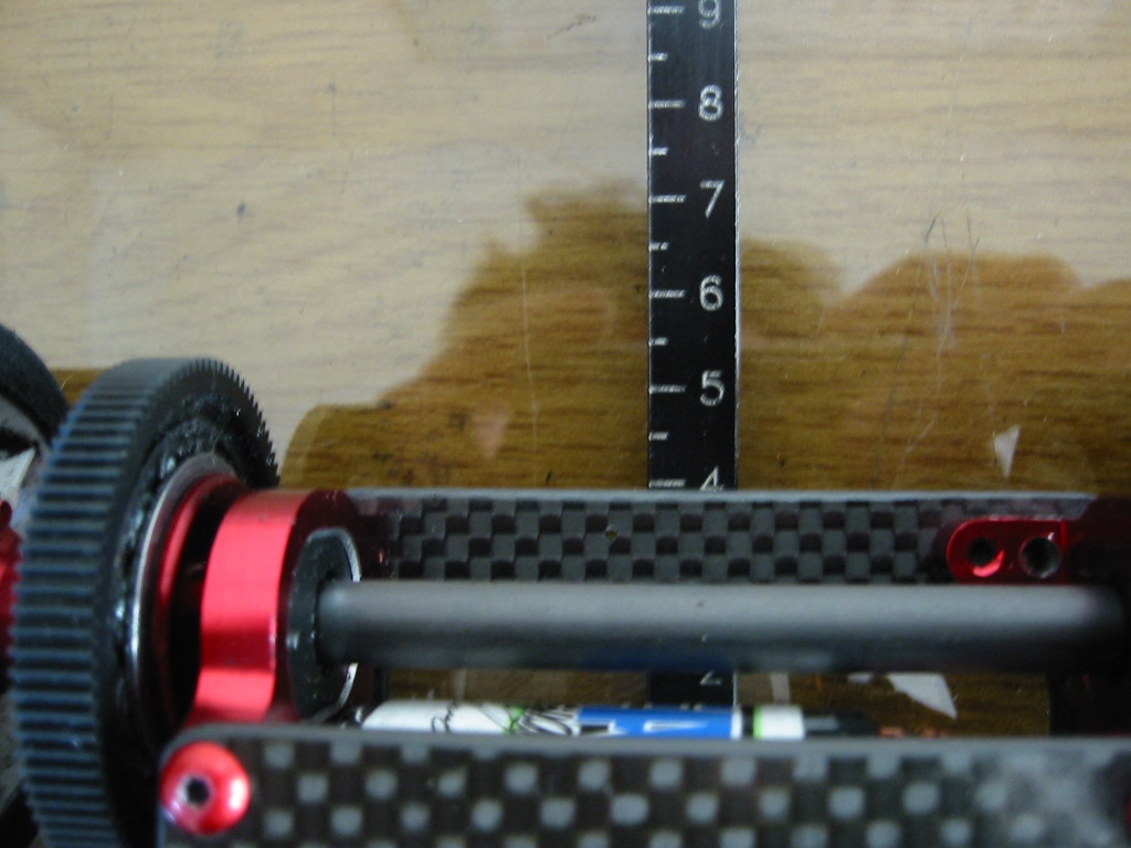
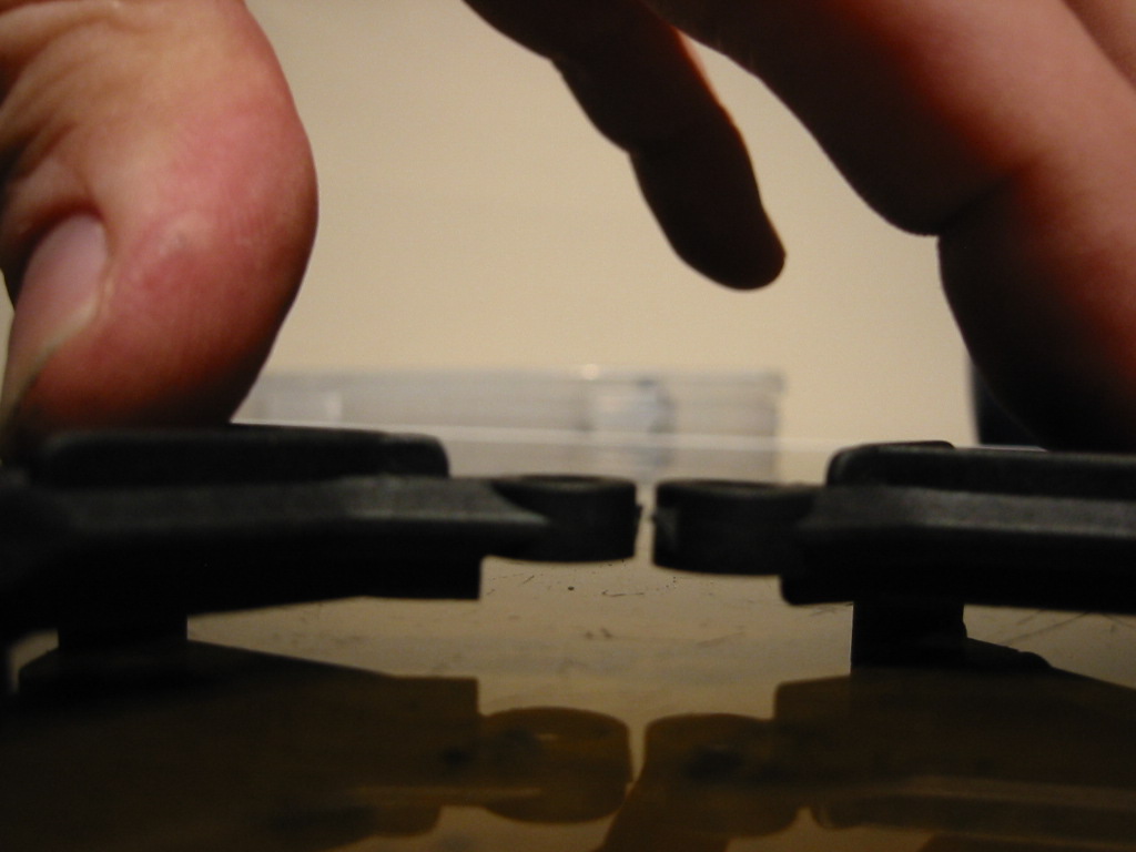
Now use your calipers as shown to make sure the front axles are at exactly the same height off the glass. If they are not I grind the front A arms until I have the a perfect match. If you have followed my previous front end instructions then there should be no issues here and this is just a sanity check. If the axles are not at the same height to within 0.25 mm (0.01 in) then you have a problem that you must address.

Step 4

Put the rear tyres on (fresh ground). The rear tweak bar and side dampers are still removed. The centre shock and spring is on as normal.
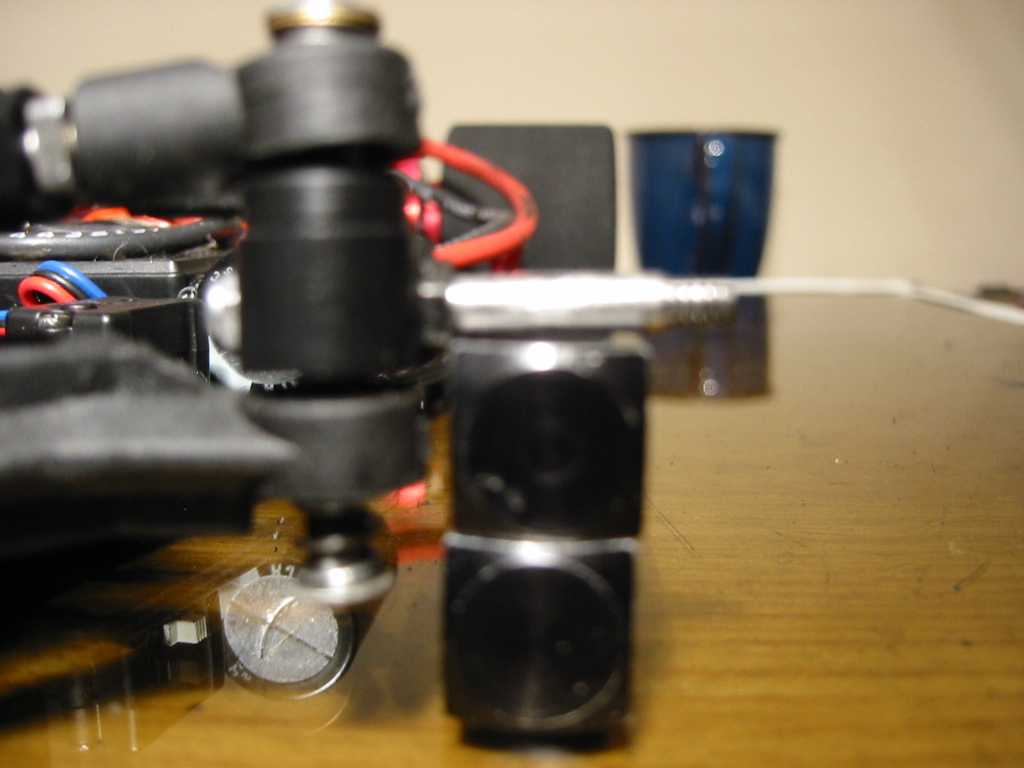
I now place 10mm blocks under the front axles (ok, I use whatever I have at hand to make an accurate 10mm block). The rear end cannot impose any tweak on the chassis as there are no side springs. Even if there is a slight error in the rear tyres, this cannot be transferred through to the front end. The lateral balance of the chassis is now purely a function of the front springs only. You statically balanced the chassis already right? (I do hope you have read the prerequisite steps ;-).
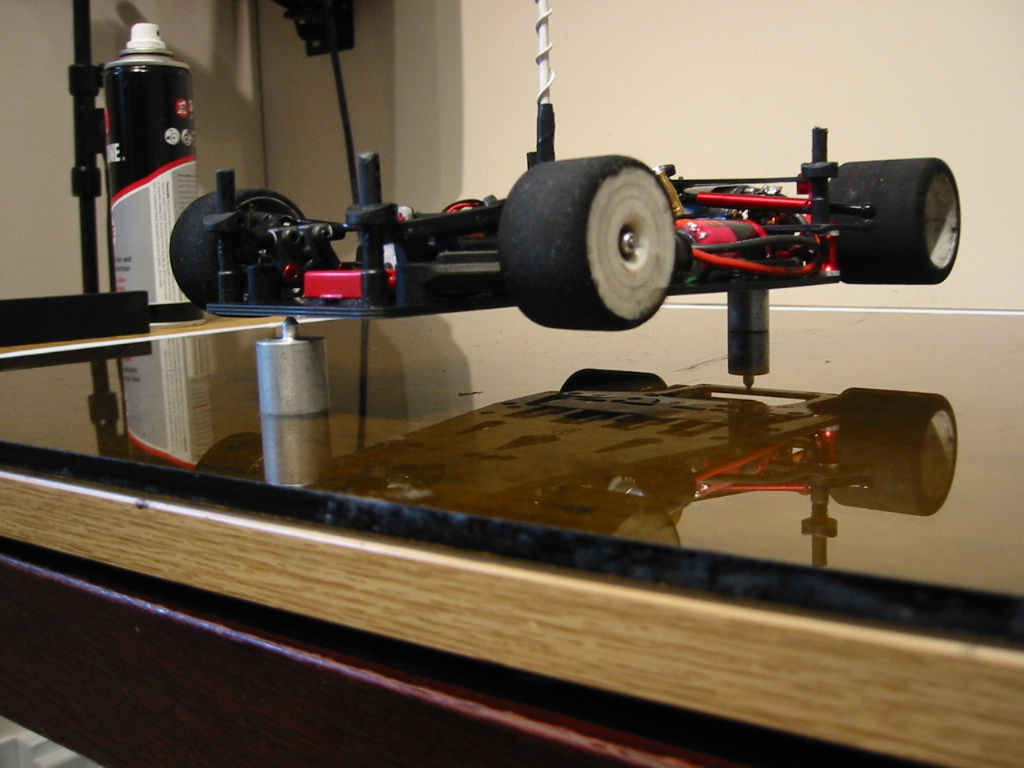

Something to be aware of … we balanced the chassis as a whole earlier but right now the front springs are subject to the full running weight of the car but the weight balance is being imposed by the front part of the chassis only.

I asked myself .. “ what if there is a balance error in the rear pod that we correct in the front (main) part of the chassis?” … Let me save you some time. I took the rear pod off and measured it’s balance complete with motor and pinion etc, it is crack on. An engineering thing that Calandra have got 100% right.

Step 5
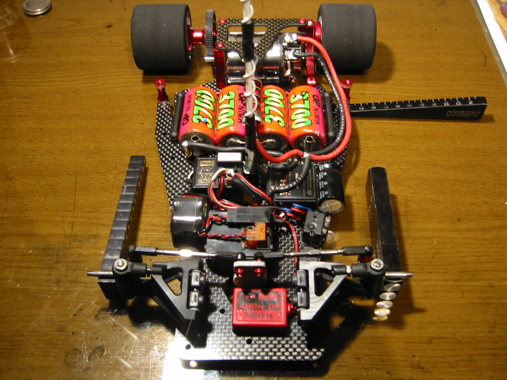


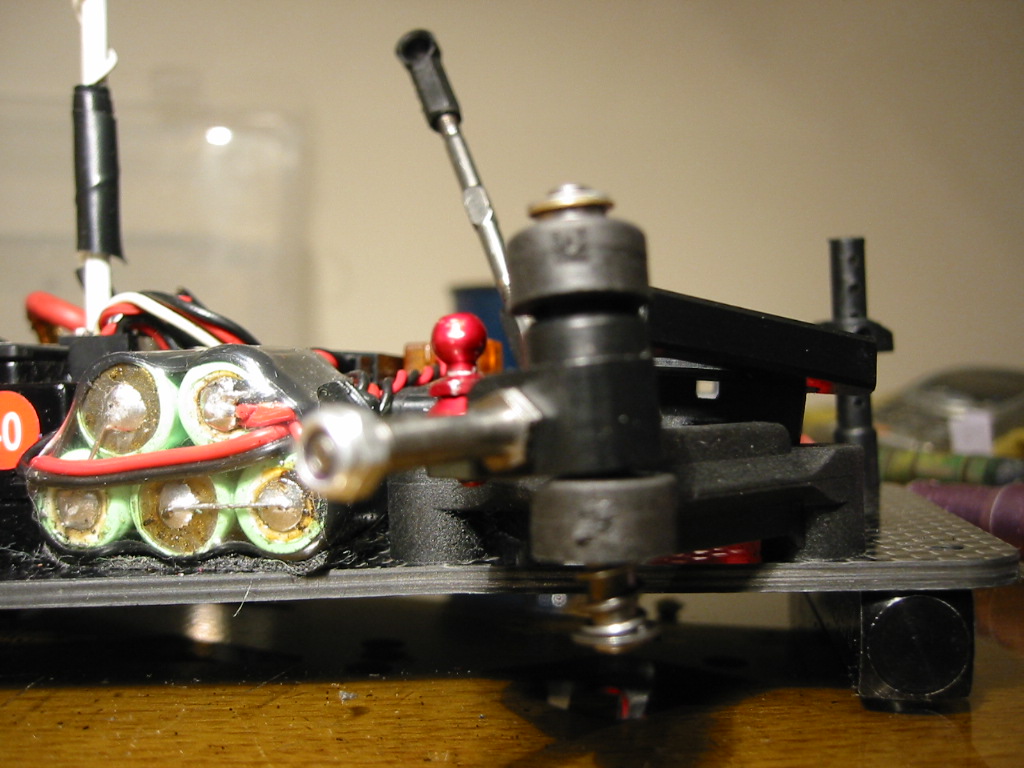
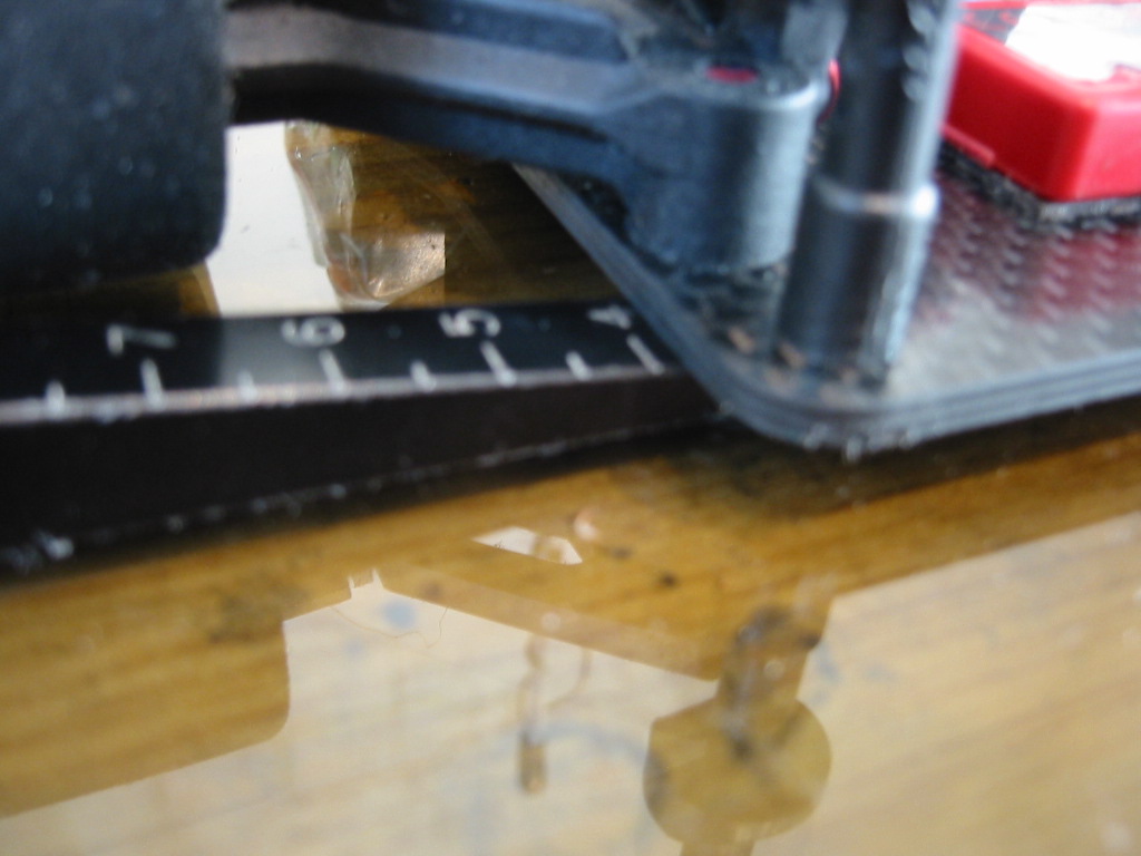
Now with the chassis loaded onto the springs at the front, any left/right differences in loaded spring length will result in the chassis not being laterally parallel to the glass. This error will be maximized at the back of the main chassis near where the tweak mounting pods are attached; this is where I measure using a “wedge” type ride height gauge.


Add or remove one or two king pin shims until the left and right reads exactly the same. You will be taking a shim out on the high side or placing a shim in on the low side.

Assuming you (just) shimmed out the slack in the king pins earlier, if you now have to add or remove more than two shims on either side to get things right at the back… alarm bells should be ringing. Something else is wrong here. Go back and check the build of the front end (separate post) and the previous steps in this section.

I generally only accept the addition or removal of one shim on one side or the other at this point to level things up.

Step 6

Its time to put the tweak brace back onto the car. But before we do this I have some tedious details to discuss!

Motor Wire Warning

Be careful. The wires going to the motor can tweak the rear pod, resisting it’s free movement. To help with this I use 14 AWG wire, not the 12 AWG I have in my kit from 1/10th scale touring cars!

I take the wires under the tweak brace. If you go over the top they can catch on the body, again introducing tweak.

Which Side Spings?

I generally use the red side spring as a starting point. I go to the white spring (softer) for less direct steering. There are two main things I have learnt about adjusting these springs.


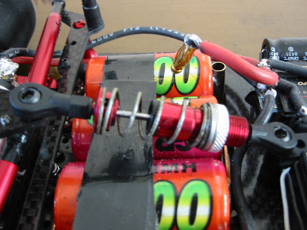
The first point is to make sure the spring sits on axis with the tweak screw and mounting. If it is off centre, you get unpredictable changes as the tweak screws are adjusted.

Now attach the tweak brace and I will come to the second point:
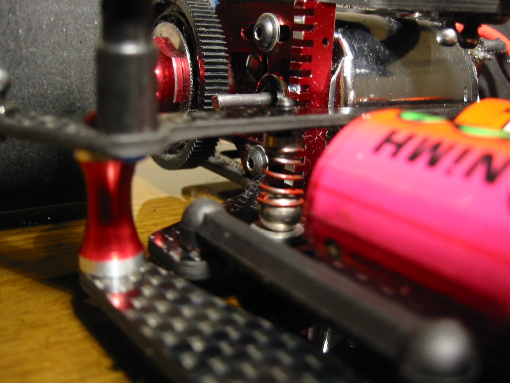
Start with the tweak screws wound right out (springs tight against the brace). Now wind down the same amount on both sides until the springs just touch the balls. I have read CRC setup notes where it has been recommended that this is how you should run the car. Ie. With the springs just resting on the balls when the chassis is flat. But…. My second main point is that I have found the car much more predictable if I load two full turns of spring tension beyond the “touch down” point.


Leave the side dampers off for now. The front end is still on the the 10mm blocks.

Now look from the rear and lift the rear pod off the ground using the centre point. I adjust the rear tweak screws to ensure both REAR wheels lift at the same time. If you are adjusting the tweak springs by more than ½ a turn on either side, alarm bells should be going off again. Go back and recheck everything because something is wrong.

Step 7

Now look from the front and sanity check the action of the front suspension. As you lift and release the suspension up and down using the centre hole at the front, you should see the same spring compression and expansion working equally on both sides.

Video: Comparing Left and Right Front Spring Action

Well done! You car is now corner weighted and applying balanced pressure left to right.

Step 8

Now comes the “coin trick”!

Why are we doing this?

To be honest, if you have carried out all the steps above, you don’t really need to do this. Remember your car is tweaked out evenly on the springs and the “coin trick” is going to lift the whole front suspension off the springs. Is this how the car drives? I think not. You already know the front axles lift off at the same height, because you checked this at Step 3.

However, assuming that you have laid the foundations by doing all of the above, the “coin trick” is the quickest way of re-tweaking the car to allow for the errors that creep into the tyre diameters after a run. No track imposes even left/right tire wear and we have to reset for this each run.

I swap the left and right tyres over each run to balance the wear rate up. After doing this I will re-tweak using the coin trick rather than do through the total “system” from scratch.

The Coin Trick

UK readers will want to find two 20p pieces or two £1 coins if you are feeling rich! As the CRC CK 3.2R is such a well engineered American car, I like to use $1 coins….. also this prevents me from spending my tweak tools at the tea bar on race day :-)

Attach the front wheels (fresh ground, the same size!) and place the car on your level flat surface.

Now place your money on the top of both front wheels, just slightly beyond the apex (by the same amount). Now lever the car up using the front centre hole s l o w l y.
The wheel that lifts first will drop the coin first. This is the high side.

Video: Coin drop on a car with bad tweak
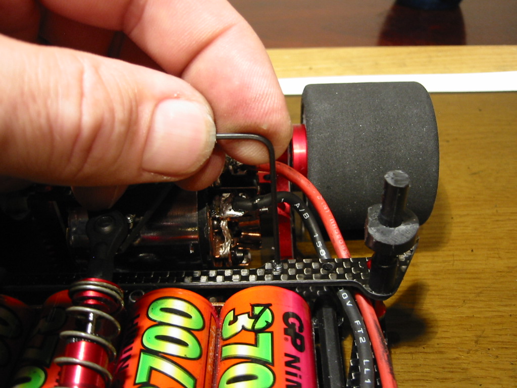
Correct the high side (coin dropped first on the left here) by winding the tweak screw down on the opposite side (clockwise turn on the right in this case). Alternatively back off the tweak screw (anticlock) on the same side as the “early drop” coin. Adjust by no more than 1/8th of a turn at a time. If you are using more than ½ a turn either way then something is wrong or it is time to re-true your tyres.


Video : Coin Drop with good tweak

Conclusion

If you join me at this point then I congratulate you! You are as “sad” as I am :-)
… but I am confident that you car is going to go straight when you power up!

Happy racing!
Saturday, December 17, 2005

Building the Associated L4 Type Front End


Introduction

I use the Calandra CRC Carpet Knife 3.2R but the following build note apply to any car using the Associated reactive castor "L4" type front end.

I am heading towards explaining how to fully tweak out the CRC Carpet Knife 3.2R chassis. Before we look at the final tuning of the whole car it is important that the Associated front end is built as consistently and accurately as possible.

Get it right!
Fractional errors and “left to right” differences in spring lengths, shimming, block moldings and general alignment within the front end will cause unpredictable handing on the track.

It took me a whole season of 1/12th racing to realise that the driving the car is hard enough on its own without the thing wanting to pull right or left under acceleration. I am not an “inch perfect” driver but I am learning to build and inch perfect car. Unfortunately, predictability measured in inches on the track needs accuracy down to fractions of a millimeter or 1/100th of an inch .. or better!

You are going to need a set of vernier calipers to make the required measurements. I use a digital one from Mitutoyo http://www.mitutoyo.co.jp/eng/products/nogisu/hyojyun_01.html

Step 1 Checking the Lower Arms

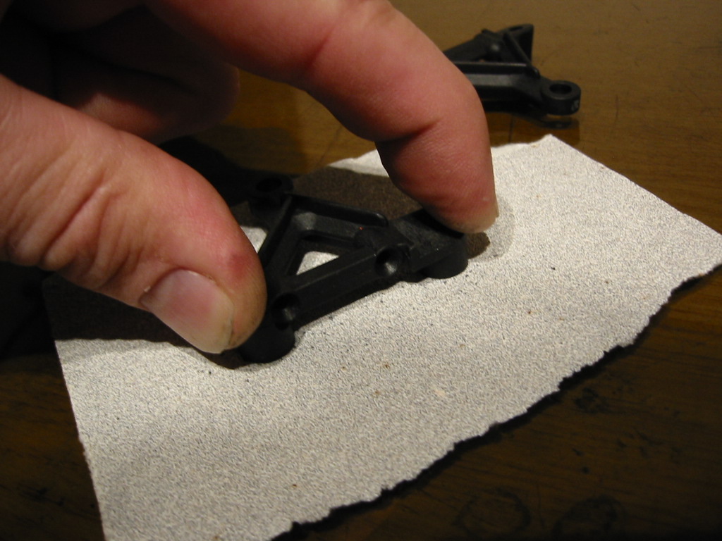
Using your flat surface (I use a 2.5 sq ft safety glass offcut), make sure the Associated left and right lower arms are the same height. You will be surprised how different these things can be. I have had two arms from the same packet as different as 1mm (0.04 in).


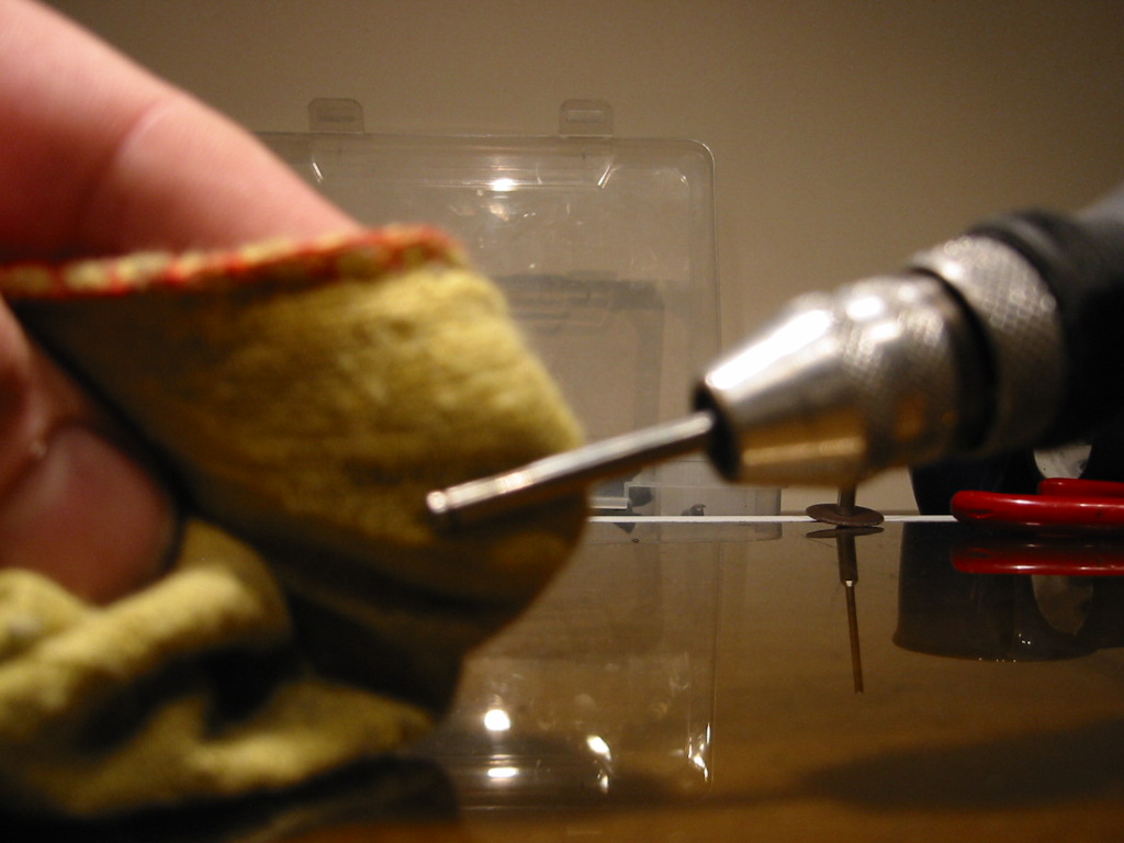
If there is a difference, you will need to “grind” the high one down until they match. To do this, lay a new flat piece of 200-300 grade abrasive paper on your flat surface and apply an even pressure, keeping the molding parallel to the surface. It is important that you do not grind an angle into the block as you remove the material.


In measuring here, the critical height is from the glass plane to the upper surface of the arm where the ball gets inserted.


Step 2 Choose your balls

I have found a much better king pin pivot ball than the standard kit part.
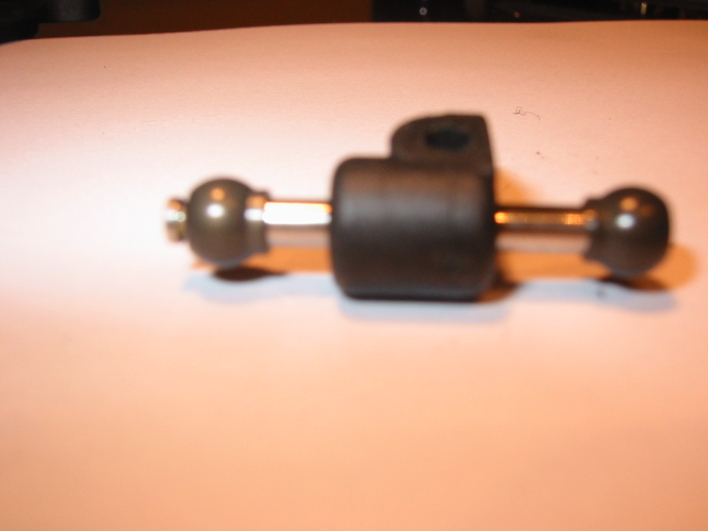
The suspension balls I use are Teflon coated. You will end up with a much freer suspension using these parts while keeping the suspension free of play.

http://rc4less.safeshopper.com/22/389.htm?692

I think IRS do these also. Not cheap but worth it… trust me.


Finally, when you push the balls into the moldings, make sure the collar is orientated towards the steering block. The collar will be pointing up in the lower arm and down in the top ball joint.

If you use pliers to force the balls into location, do use some folded paper to prevent the pliers from causing damage.

Step 3 Trim the lower arms

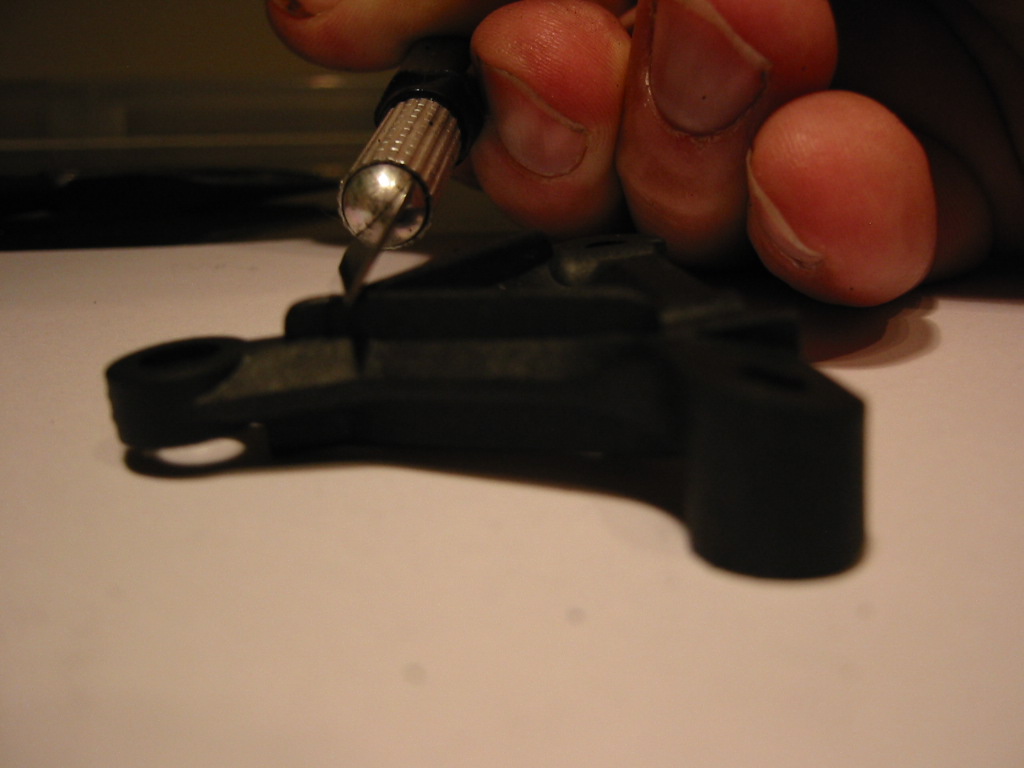
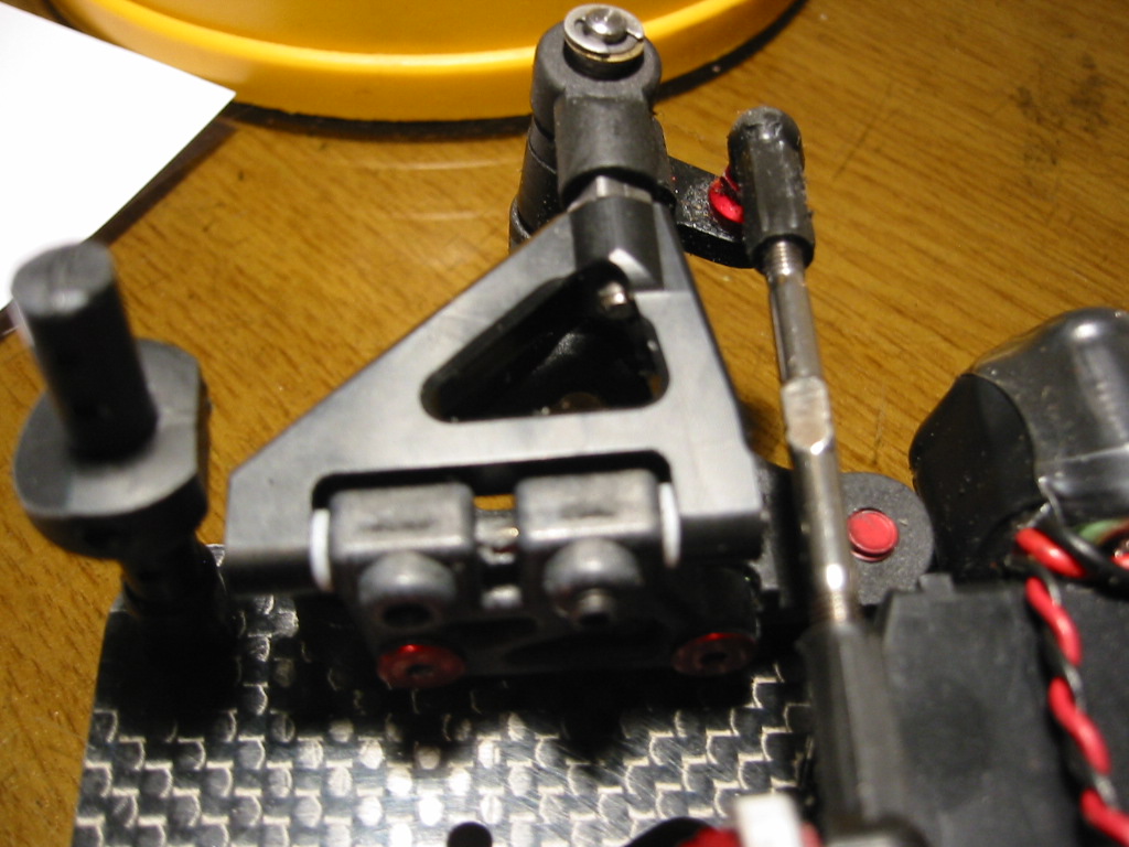
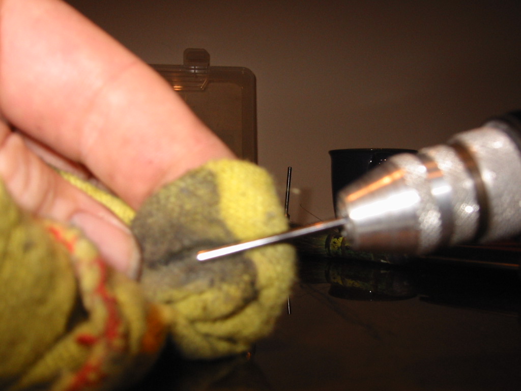
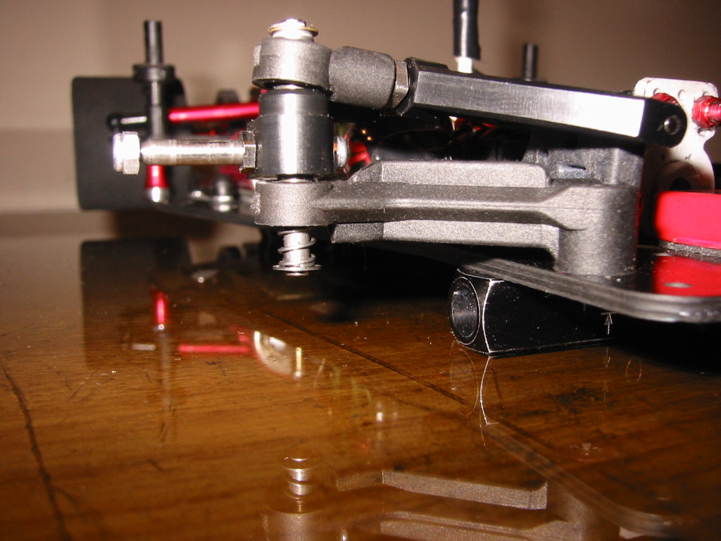
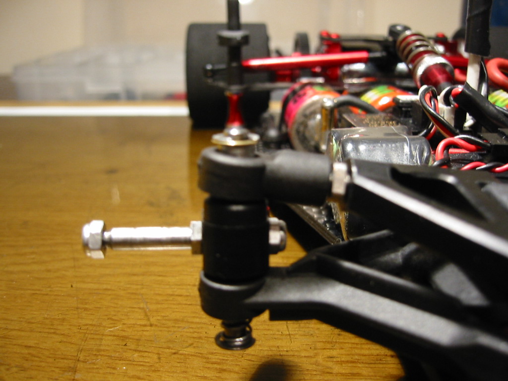
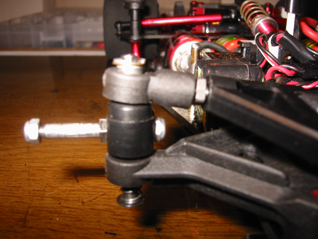
If you use the CRC front axles (as I am sure you do.. the titanium ones are great!) the securing nut on the inside of the front block will hit the lower arm on full lock so some trimming is needed here. The two photos below show this trim.


Also when the suspension is built the steering block must ride top and bottom on the metal pivot balls, not the lower arm or the upper ball joint plastic moldings.

The castor of the steering block (as a result of the king pin angle) tends to make it bind on back edge of the lower arm while steering, lifting it off the lower ball. To stop this, trim some material off of the lower as shown.


Step 4 Polish the king pins

It’s a simple thing to do but it makes a real difference to the feel of the suspension. Make sure the king pins move freely in the pivot balls. I use a house hold metal polish to do this. After polishing it is important that all residue is removed. If you fail to do this the polish grit itself will become a binding agent in your suspension.

The king pin may be burred where the slot for the E clip has been machined. This makes the king pin slightly oversized and it may scratch the ball as you push it through. A light touch with abrasive paper around the ends followed by a polish will solve this problem.

The king pin moves through the lower arm ball like a piston as the suspension compresses on the spring so it is important to make sure this area runs especially free.

It is also important for the king pin to move freely through the steering block. I use the optional Delrin CRC block. This is more accurate than the stock Associated molding.

http://www.teamcrc.com/crc/modules.php?name=Shopping_Cart&file=product&c_op=viewprod&prodID=7718834

… the reaming for the king pin is really nice and free… but…. There is a problem here. The Delrin blocks include stock axles but if you screw in the CRC threaded axles, the king pin hole tightens up and the suspension will bind.

After screwing in the CRC axles it is necessary to ream out the king pin hole to an accurate 1/8th fitting again. You can do this by hand using a 1/8th drill or (even better) a 1/8th reamer. Alternatively, just stick with the stock axles that come with the blocks.

Step 5 Polish the upper pivot pins

I have started to use the CRC optional Delrin upper arms as they are more accurate than the standard associated ones.

http://www.teamcrc.com/crc/modules.php?name=Shopping_Cart&file=product&c_op=viewprod&prodID=7718833

The upper pivot pin can bind on these arms, mainly because the tolerances in the pivot hole on the CRC part is tighter.


Polish the pivot pins, especially at the ends where the bearing surface is made with the upper arms. You do not need to get the pin to run free in the reactive castor angle block (the 0 degree, 5 degree, 10 degree part), you will probably want to lock the pin in place with a grub screw here anyway to hold the pin fast.

When assembled, the top arm should pivot around the pin with no noticeable friction, damping or binding.

Handling note

I normally run the 10 degree reactive castor block which does offer the most aggressive steering out of the three (10, 5 and 0 degrees). I will reduce to the 5 degree block if the car is too snappy on the front.

Step 6 Shim and Spring the King Pins

Handling note

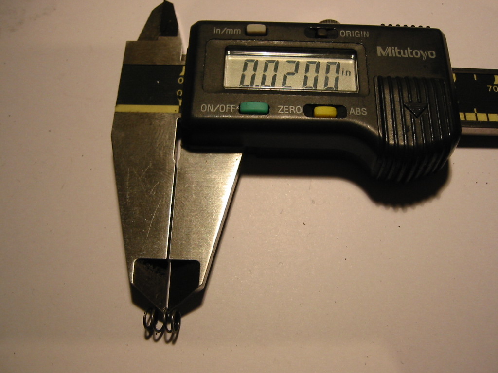
My starting point is to work with the 0.020 in. front spring. The spring number is referring to the diameter of the wire used to form the coil. The higher the number, the thicker the wire and stiffer the spring. Optional springs are as follows:

0.018 in. Soft
0.020 in. Medium
0.022 in. Hard
0.024 in. very Hard!

Spring Errors


First pick two springs with the same thickness and measure them with your calipers to double check yourself. I know this sounds stupid but I have made mistakes in the past and ended up running different springs left and right!

It is also important that both the springs are the same length to within 0.01 in (0.25 mm) which is the thickness around two shims. If the springs differ by more than this I would assume that one has collapsed and is damaged. Get a new pair.

Adding Shims

I like to shim the king pins so the play is just taken out of the assembly when there is no load on the suspension. The shims are applied to the top of the king pin between the top ball and the upper E clip. Do not use motor shims as their outside diameter is too large and they will bind up in top ball joint molding.
The correct shims for this job have an outside diameter of 4.92mm (0.1940 in).


The two shims sizes I have are 0.11 mm (0.0045 in) and double that at 0.22 mm (0.0090 in).

If you use the Teflon coated balls (as mentioned above) with the 0.020 spring and have trimmed the back part of the lower arm also, a good starting point for the shim stack is 2.22mm (0.0870 in). The problem with giving this measurement is that there are so many variables including the balls, steering arm, king pin length and even the E clip thickness.

Step 7 Final Check

Finally mount the front end on the car.

Adjust the servo links for Zero degrees toe. Then use a camber guage to get to set 1 degree of negative camber.

Always remember, when using the turnbuckles to adjust the front camber, ensure the top ball joint part finishes inline with the king pin. That will mean that it is angled back slightly.

Finally check that the shims have just taken out all of the king pin play and that the suspension has the same free feel when you compare left to right.


Cheers

Mark

Friday, December 16, 2005

CRC 3.2R Centre Shock, Spring and Pod Droop

Centre Shock, Spring and Pod Droop


The VCS centre shock and its spring controls the “bend” in the chassis (around the rear pivot point) when power is applied by the motor. Under throttle this spring is going to compress. It will also compress over the bumps.

There is no limit to the compression of this spring other than the chassis bottoming out. I guess you could fit a limit cylinder on the shock shaft but I have never tried this. My gut feel is that the compression evident with the car on the track is a few mm at most.

We do however limit the backward movement of the pod using the length of the VCS shock and its ball joints. The trick is to get the shock length just right according to your required backward movement. This back tilt allows “lift” in the chassis height above the static setting, maximised around the cell area.

I have read recommendations that this allowed “lift” should be around 1mm, however, I have been tuning for no lift at all. I find that the rear end is more predictable this way.

Broken Shocks

The pod back tilt or lift is limited by the shock shaft itself. If you tune for no lift or only 1mm, a crash can cause the chassis to pull the innards of the shock out, which is not good! With the standard Associated VCS shock, the only thing holding the shock together is the plastic “E” clip.

I have started to use the CRC Dura Shock which solves this problem http://www.teamcrc.com/crc/modules.php?name=Shopping_Cart&file=category&category_id=24

I have never had a crash failure with this type of shock.

Improving Shock Balls

Removal of the battery pack can require the removal of one end of the VCS shock. I see people in the pits killing the ball joints with pliers. This cannot be good for the reliability and accuracy in this area.


I use the threaded stud type of ball joint used on XRAY touring cars. These are the 303220 and 303240 parts found here:
http://www.teamxray.com/teamxray/products/proddesc.php?prod_id=394&kategoria=1290

Measuring ride height on a CRC 3.2R

Measuring ride height

Before we can do a fine adjustment on chassis tweak we need to get the basic ride height and rear pod droop set roughly right.


I measure ride height in 5 places as shown in the pictures. These 5 locations tell you a lot about the car. You will need a “wedge” type ride height gauge, not a stepped one. The wedge gauge will allow you to measure ride heights to within 0.2mm. This is the one I own: http://www.hudy.net/xhudy/products/proddesc.php?prod_id=157&kategoria=64

A word about chassis rounding: I notice many people round off the edges of the chassis for a smooth look. Yes ok, this looks nice but you loose the accurate edge against which you can measure ride height…. So I don’t bother.

As you can see in the pictures (4mm ride height intended), I expect to be able to tweak the car out (full instructions later!) and end up with a ride height that is equall from left to right within 01. to 0.2 mm.

Starting Tyre Size

Accurate ride height and setup can only be achieved if you have accurately ground tyres. A good starting point is with 50mm rears and 45mm fronts on the CRC. I like to race nationals with tyres much smaller than this but I start here for club meetings. If you don’t have access to a tyre truer then your ability to set up a 1/12th car is going to be severely limited.

True your tyres and use the rear pod axle spacers and front block shims to get the ride height around 4mm as a starting point. I tend to run ride heights between 3-4mm depending on the quality of the track.

A warning about front block shims.

I use the Fibre Lyte shims http://www.fibre-lyte.co.uk/fl/cars/callandra/calspa.html
The idea is that you can push in the shims in just by loosening the front block screws but there are problems here.

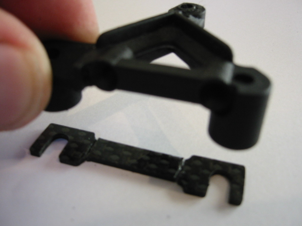
I have found that the “U” shape of the shim allows the block to distort into the open part of the U…. and no, I do not over tighten the screws. This leads to unpredictable geometry at the front.


Bad Good

My solution is to cut the shims into four separate “U’s” and turn them through 90 degrees so the block material inboard and outboard of the screw is supported.

CRC 3.2R Chassis Setup. Static Balance

Chassis Balance

Tweaking out the chassis for predictable handling on a 1/12th car is going to be dependant on a good static balance from left to right as a starting point.

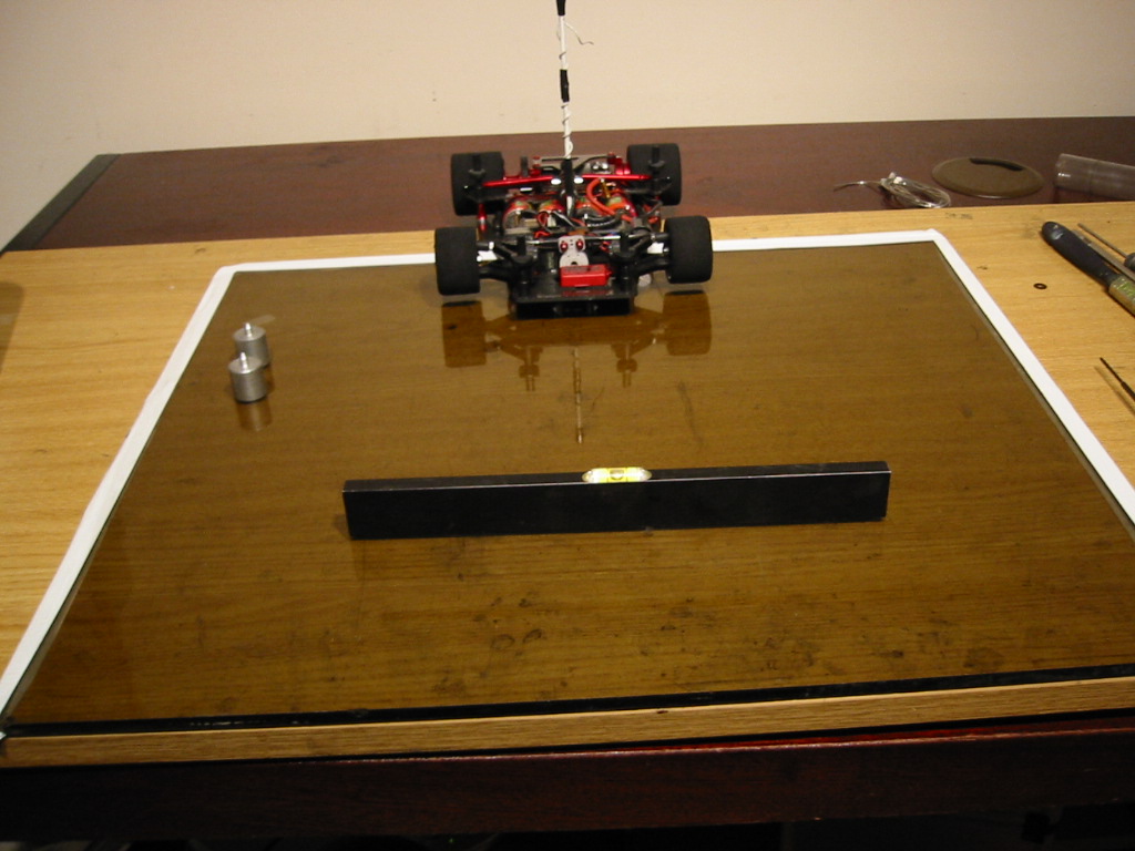
Start with a flat surface which is level on your workbench. I use a piece of safety glass (pop down to your local glazing company for an off cut). Level the glass out with a spirit level.


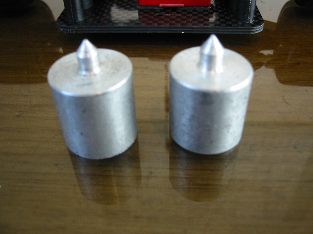
The chassis will need indentations or small holes at the front and back on the centre line of the car to allow the correct location of balancing pins. The rear hole needs to be located on the back cord of the rear pod. I cannot remember if the CRC rear bottom plate has this hole and the front definitely does not.

Use a set of calipers referenced off the inner edge of the rear wheels to find the centre line of the rear pod, the whole pod is off centre so this is the only reference that makes sense. The centre line at the front is easier to scribe from the edges of the chassis.

Now comes the balancing bit...

Set the car up with all your gear, wheels/tyres on and set for correct ride height and rear pod droop (more on this later). Batteries in, pinion on and wiring all plugged up ready to go. Just don’t stick any of your electronics in yet.

The variable items that can be moved around will be the speedo, radio receiver, RX battery pack (if you use one) and Personal Transponder (PT). I place the PT last to fine tune the chassis balance by moving it between the steering blocks at the front.

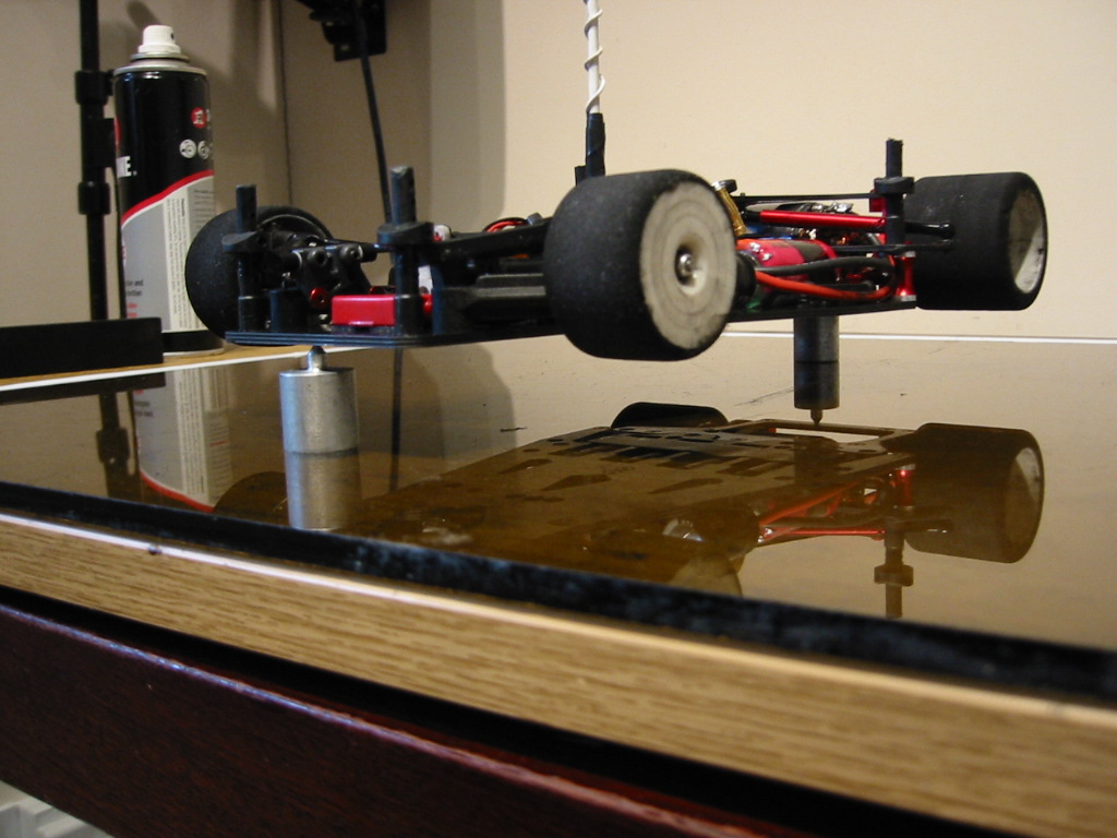
I have made a pair of alloy balancing pins which locate into the holes made earlier in this discussion. HUDY make these things if you have need http://www.hudy.net/xhudy/products/proddesc.php?prod_id=173&kategoria=64


Place the car on the pins and use a spirit level over the back tyres to locate the car parallel to your flat surface. Now when you remove the sprit level, the car will obviously fall over on the heavy side. You can now move your electronics around until the car balances perfectly on the pins.


Finally locate all your gear and stick it down. You are now ready to move on the next part of the chassis setup.

Brushless Update Nov 2006

Here we have a problem, the approach above is valid for your brushed modified and 19T motors. This is becuase the rear motor pod is almost perfectly balanced with "traditional" motors. However...... brushless motors carry a weight unbalance where the pinion side is light compared to the connection side.

You may be tempted to try and correct this by shifting weight around in the font part of the chassis. This is an error in my opinion. The front part of the chassis should be statically balanced independant of the rear pod.

A full discussion of this can be found here: http://www.rcracechat.com/vb/showthread.php?t=23696 ... some of my collegues are arguing with me here which is generally a lost cause ;-) so I will reprint the main points below:

*************

Set the scene: If you take your rear pod off your car and keep it complete with rear axle, wheels, average 10 turn modified motor and pinion and then pop it in balancing posts.... it will balance (left to righ lateral balance), pretty much spot on. So.... join the car up again and put the whole thing on the balancing posts and balance it out by the arrangement of the electrics and you have a tricked out car. I have already documented this all in the blog. Now the brushless: Ooooh ... interesting (come on, if you are down this far you are interested) again my brushless post on 12thrc tell us that my LRP brushless setup is about 30g heavier than the brushed. This is not news but the balance of the motor is different. There is a lot more weight at the (I was about to say commutator end!) ... at the sensor wire/connection end, away from the pinion. This unbalances the pod. As a result, if you then correct this in the front part of the car you end up shifting weight over to the pinion side of the car. In fact, I can only achieve overall balance by adding a 5 cell RX pack right over on the pinion side. So.... I am left thinking... is this the right thing to do? When this lot sits down on the deck the front chassis is applying a slight twisting force through the tweak springs to corner weight the rear tyres. So I have decided to remove the pack which balances the front part the the chassis (take off the tweak brace and you can pivot the chassis around your front end lifting point and the rear pivot ball) but leave the car overall with an inbalance due to the pod.I think the real fix would be a modified pod with the bulkheads moved over to the pinion side (yes resulting in a shorter diff side axle offset and a longer offset on the other side). However this is really NOT an easy win.Also in Worlds brushless trim without my pack the car is at 885g (that is with my 3700s in!). The limit is 865g. If I were to run the pack and the 4300's I am going to be well over 900g.