Sunday, March 12, 2006

Going Brushless; Report from 1/12th Scale 2006 European Champs


Going Brushless: Report from 1/12th Scale 2006 Euros

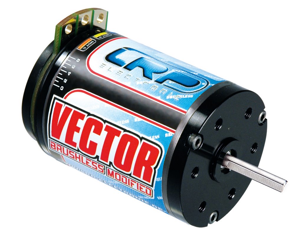
During the 2006 European 1/12th Scale Championships in Gran Caneria, I had the chance to test out the new LRP Sphere Competition Brushless ESC in combination with the LRP 4 Star Vector Brushless Motor.


For more information on the 2006 1/12th Euros see http://www.ec2006.org/
For background spec and technical info on the LRP Sphere/Vector Brushless system see http://www.lrp-electronic.de

Currently in the UK 2005/2006 season, BRCA sanctioned events for 1/12th scale do not allow the use of Brushless systems. As a result of this not many UK 1/12th racers have gained any significant brushless experience so the Euros were going to be a watershed.

The Base Modified setup

I arrived for the Friday practice sessions with my standard setup for modified loaded into the car. I use a KO VFS Competition ESC with various motor options. My most used motor has to be the Corally Black Series 10*2. This motor seems to have the best run time for me when timed around 11 degrees and pulling 40mm/rev.
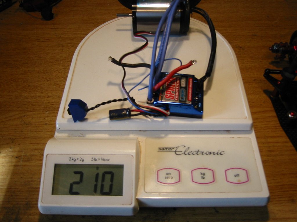
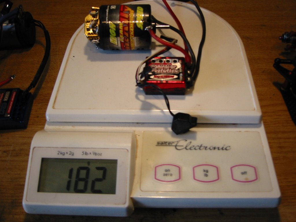

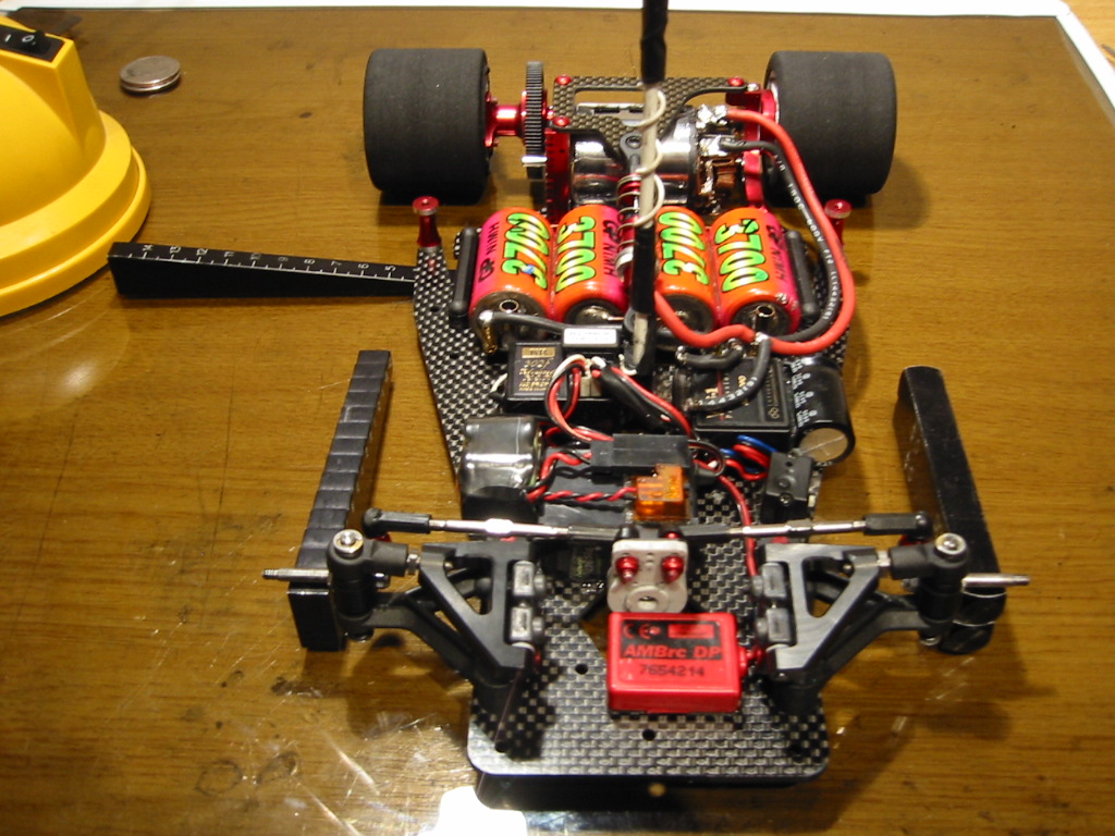
As you can see, the brusless setup is 28 grams heavier than my modified brushed setup.

Drive Smooth

By nature I am a smooth driver. I tend to not throttle jam and being a bit of an “old man” I like to allow the car to roll around for the first 2 mins at least. I will use the sweeper at the end of the straight to save energy and try not to feel the end of the sick too much until the last 4 mins.

End of Season Cells

We all know that cells loose capacity as they age with charge/discharge cycles. I must admit that I aimed to compete with “end of season” GP3700 cells. These cells have lasted me the whole UK BRCA national series running both 19T and modified events.

I do keep an eye on things and I know that from testing all my packs prior to the event , they charge to around 4200 mAh (4.5A charge 0.04 pack delta on a ProTrak charger). Discharge capacity for the 20A cycle on the Protrack is in the order of 3600 mAh (0.9V per cell cutoff). Hence these cells are not the best but they are not garbage either.

Run Time Issues

As the grip came up during Friday practice and by the 4th round with my brushed setup I started to dump! It became obvious to me that run time was going to become a major stress for me.

After the first grading round I was 21st overall (this was not going to last! I am one of those drivers cursed with the ability to drive a new track reasonably quickly but then not improve!)

The Euros track was as large as we see on the UK scene with the top pace being around 37 laps.

I realised that my duration situation was just going to get worse…….

LRP to the Rescue!
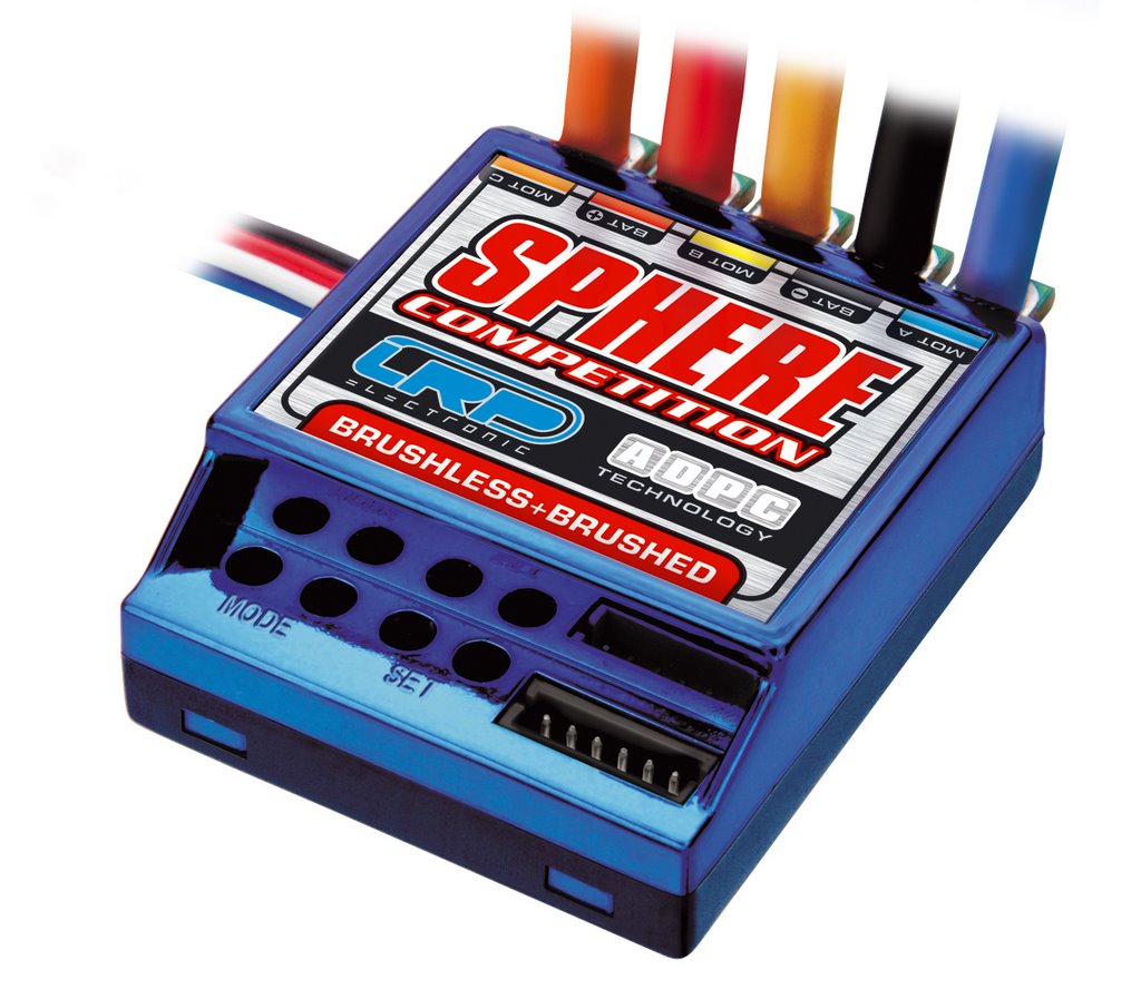

I had already arranged the possibility of testing the LRP Sphere/Vector system in association with Helgar Racing (the UK distributor of LRP) and LRP. The LRP Company had Reto Konig (R&D Manager at LRP) in attendance giving technical support to drivers at the meeting.

Reto hooked me up with the Sphere Competition ESC and the 4 Star version of the Vector brushless motor. I only had the time between adjacent timed practice rounds to fit the combo to my CRC Carpet Knife!

Fitting the System

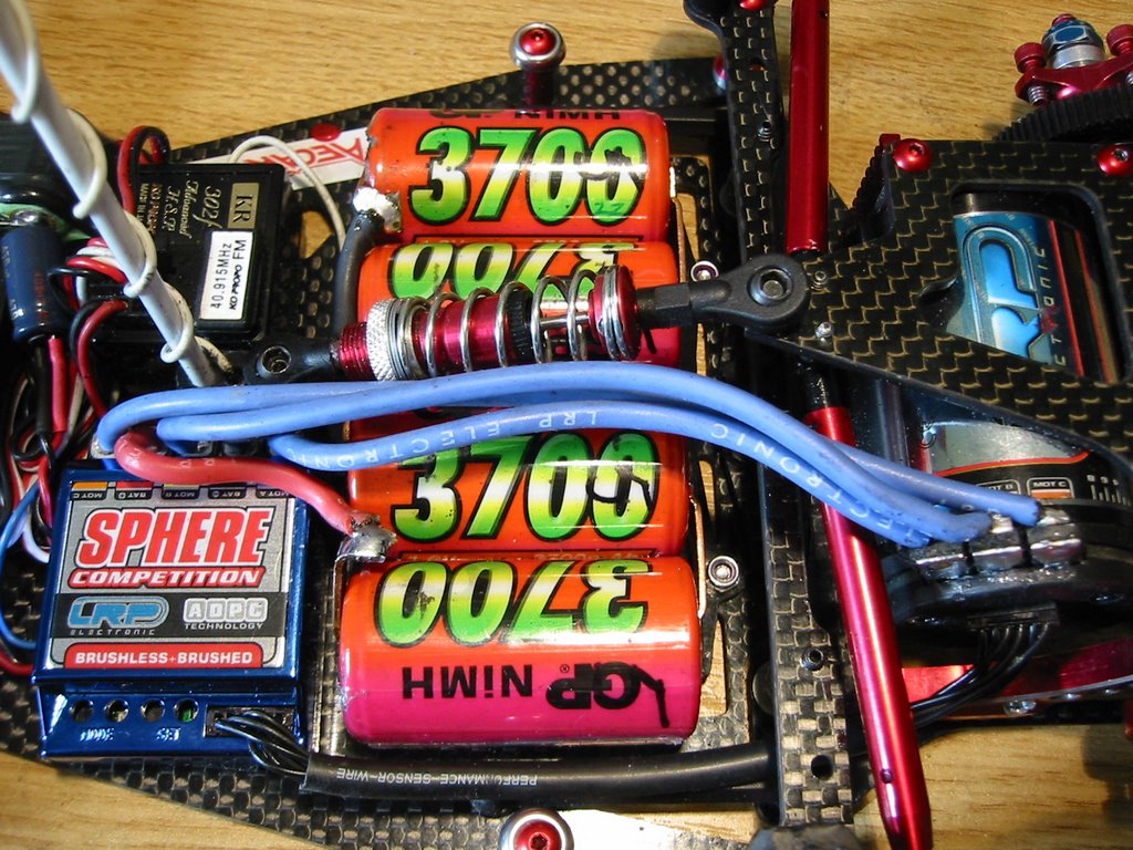
Reto had already fitted a thinner 16 AWG wire loom more suited to 4 cell 1/12th scale cars. None of us would want to run the 13 AWG wire that the system is supplied with (suitable for TC racing), there would be too many tweak issues to the Motor pod on a 1/12th scale car.

The ESC also had a small 470uF 16V power capacitor pre fitted to small power wires coming from the side of the unit.
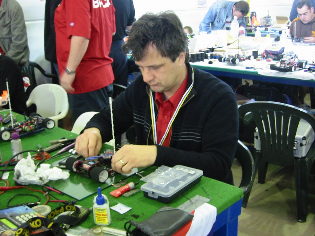
My first fitting attempt was a failure (!) mainly down to me rushing to get the car turned around for the next qualifying session. Less haste and more speed was required.

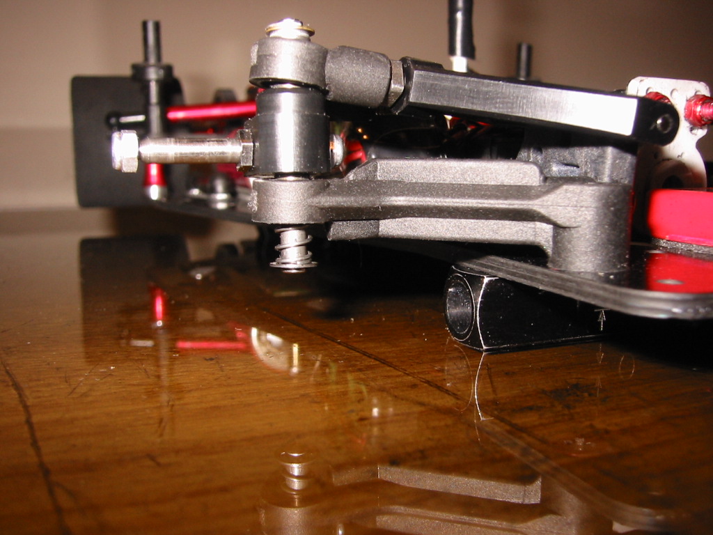
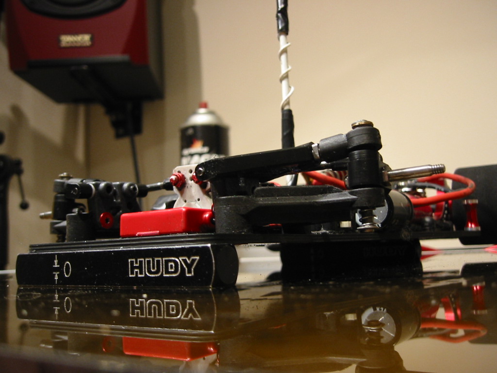
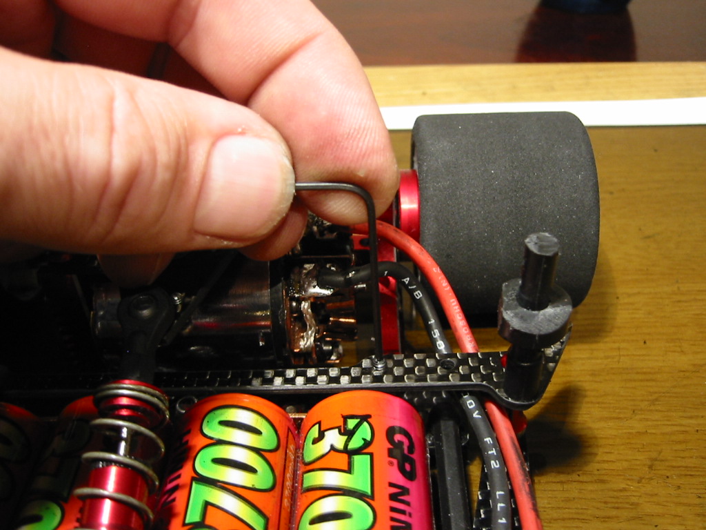
In the end I settled for the layout you see in the pictures with the sense wire running under the tweak brace and the three motor power cables following the centre line of the car.
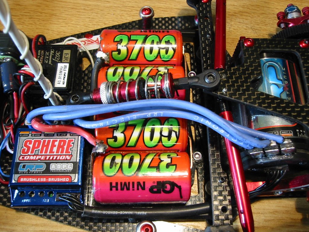


LRP make the sense wire in two lengths (Part no 81920 is 100mm and 81910 is 200mm). I had the shorter 100mm harness which is just right but only just long enough, you have to fit the ESC as I have shown or the short sense wire will not reach.

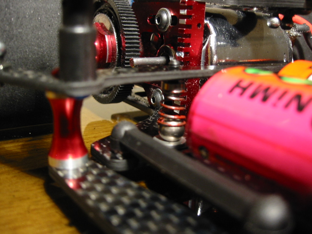
I made sure the motor wires did not obstruct the damper tubes, restrict rear pod movement or catch on the underside of the body in any way.
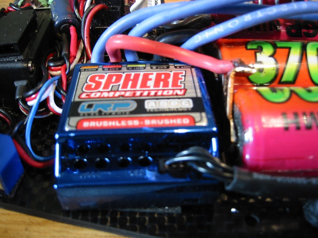
The LRP Sphere Competition controller is the lowest profile brushless unit available and does not need a fan or heatsink for 4 cell 1/12th cars. This is good news as it just fits under the Parma Zytek shell that I tend to use. This shell is one of the lowest shells at the sides so if this works for me it will work for any body I think.

I just managed to turn the electrics refit around in time. The rest of my tyre and car prep was a bit of a disaster due to time pressure but I managed to do it all in the one hour available. To be honest, people have said that fitting brushless to a 1/12h car is a stress, I did not find this to be true. Give me two hours not under meeting pressure and I would have a neat job done and time for a cup of tea and a sandwich.

The Basic Settings

The Sphere programming user interface is similar to the Quantum QC3 and Nosram clones so it was familiar to me even without the manual.

Reto had preconfigured the speedo with the following settings which I did not change.

Mode 1: Auto Cell System Setting 2 = NiMH 4-7 Cell racing mode
Mode 2: ADPC Power Profile Setting 3 from 6 Levels increasing punch
Mode 3: Initial Brake Setting 2 from 6 Levels increasing initial brake
Mode 4: Automatic Break Setting 2 from 7 (0-6) Levels increasing drag break

I don’t use breaks in 1/12th scale so the Mode 3 setting was irrelevant to me. This is not true of the Mode 4 setting. Brushless motors do not magnetically “cog” so it is important to simulate the natural breaking of a modified motor to create the same weight transfer and slowing as you lift off the throttle. LRP (Reto) advised me that the Auto Brake setting of 2 would be like a “standard” modified motor so I went with that.

Gearing

I was advised to start at 30mm/rev (wow.. that’s low!) so I did exactly that. I had to buy a few new pinions and ended up on around 21/96 on 45mm dia tyres. Remember that this is the 4 Star motor here.

In Use

I took it easy for the first two laps…. Then started to push….. oh its fast! Feels like my 10*2 … more top end speed with a really smooth power delivery. The auto break felt no different to my brushed motor and I was straight onto my previous lap times.

So… after 4 laps I decided to “drive it like I stole it” just to see what would happen. I nailed the thing for the remaining 7 mins. It was not pretty and I am not proud of myself ;-) but I had a lot of fun.

The car just ran and ran to the end. I lifted it off the track and the motor was warm but not hot to touch. The post race discharge (now there is a novelty) showed me coming back with 300mAh left in the tank. Oh Joy.

Now…. through Saturday (qualifying) and Sunday (finals) I did not touch the motor or even think about it. I did not dump once and in fact, I won the first leg of my final (from 5th) in the last lap as the leader dumped in front of me ;-) I had legs to the end.

After 3 legs I was 3rd overall in the D final. Not bad seeing Marc Rheinard had come out to play with the CRC trinity and the 12 disciples thrown in for good measure.

In hindsight maybe increasing the Mode 2 power profile from 3 to 4 may have been interesting .. oh well, next time.

Conclusion

To my mind the LRP Sphere/Vector Brushless system is a total winner. I spent an enjoyable two days of competitive racing at the Euros without the anxiety of dumping and I did zero motor maintenance.

I was left in peace to think about racing lines, car setup and tyre choice.
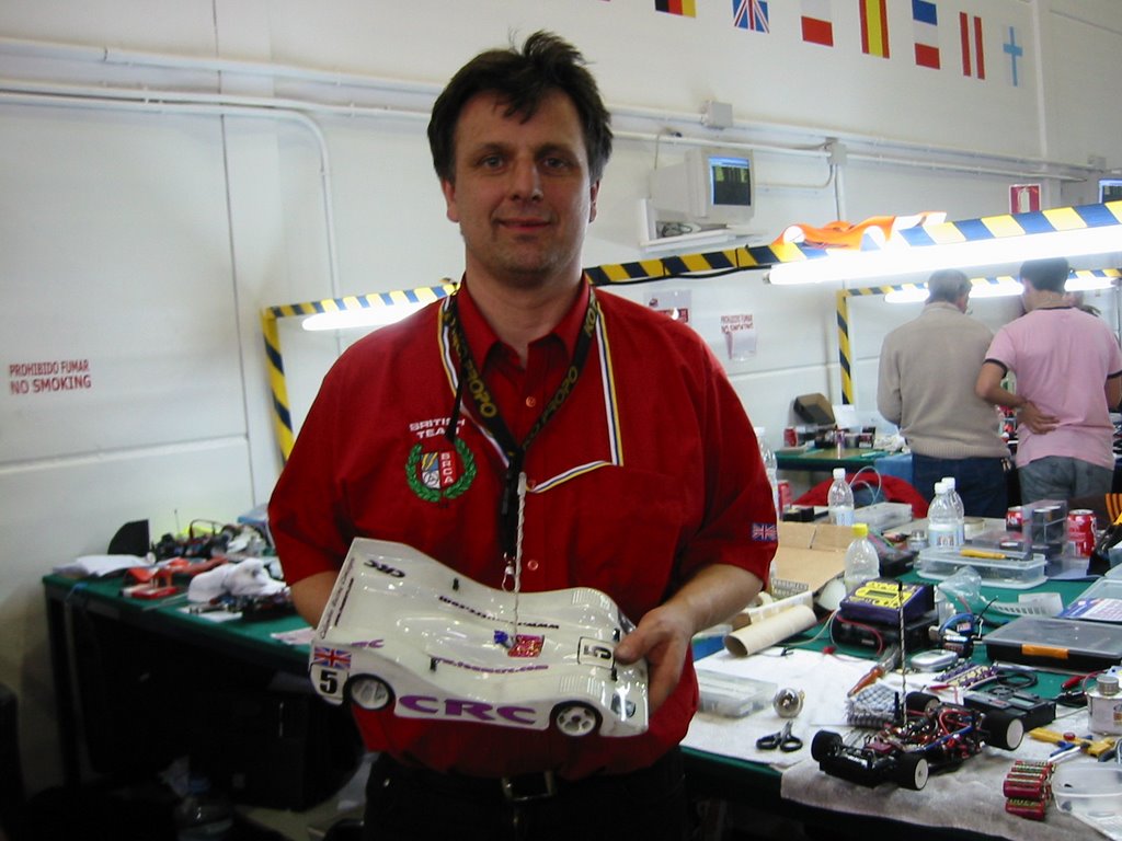
It is true that the top three cars in the A final (Team CRC!) were running brushed motors and maybe it can be argued that with brand new top class cells and Oscar Jansen sat at your pit table brushed is very fast indeed. I am mature enough to realise that my failure to make B and A finals at this level has nothing to do with horsepower. I am simply not good enough, and this may never change. I just want to keep on learning and enjoying my racing. The Sphere/Vector combo just added to my enjoyment of the whole weekend.

I really hope we pass Brushless for the 2006/2007 BRCA season. I know how I will be voting.

In preparation for the last UK modified national at Chesterfield I have taken the LRP system out again and it is sitting in front of me without a car. Oh well. Better charge the comm lathe pack again……

Many thanks and regards to

Helgar Racing http://www.helgerracing.com/
LRP Electronic http://www.lrp-electronic.de/
Reto Konig
David Splashett

Tuesday, December 27, 2005

Preventing and Repairing Rear Tyre Chunks

Preventing and Repairing Rear Tyre Chunks

One of the things I like about 1/12th scale racing on foam tyres is that the grip remains consistent independent of the age of the tyres or the number of runs they have done.

In the UK we only run odorless additives which are less aggressive to the rubber, the track and the health of the people at the meeting! I have completed a whole meeting on one set of foams for example. Readers of this article may want to argue about the benefits of rotating to a fresh set of tyres every run within the racing day to prevent the tyres from becoming over soft.

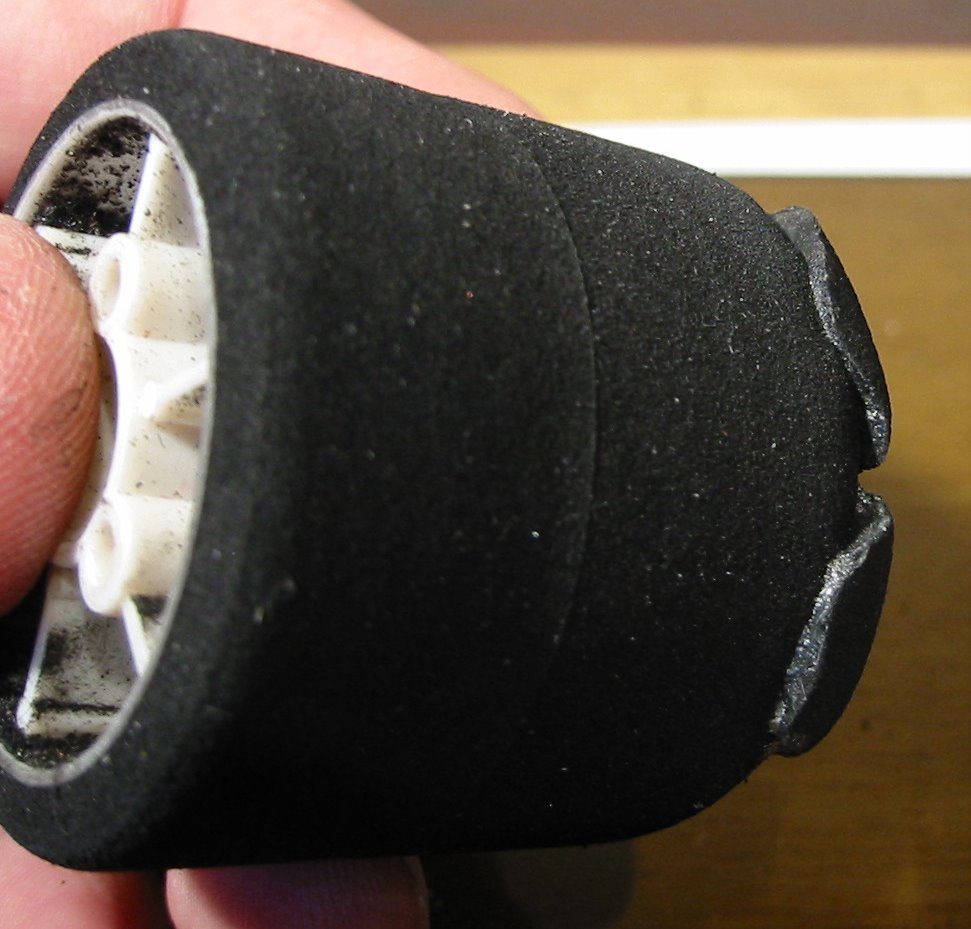
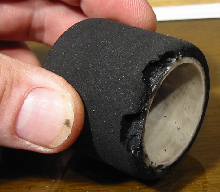
My objective in this article however is to demonstrate how “chunked” rear tyres can be prevented and even repaired. Tyres are expensive and I hate the feeling when you come back from a heat or final with the outside edge of your precious foam rubber with huge bites out of them.

All it takes is a little care and time. You can save yourself some serious beer money!

Preventing Chunking in the First Place

Well the first rule is not to hit anything and do not get hit! Failing this, tyre checking and maintenance is going to be required after every run.

In general only the rear tyres will have chunks ripped out of them. The fronts normally come back chunk free but it still pays to check them over.

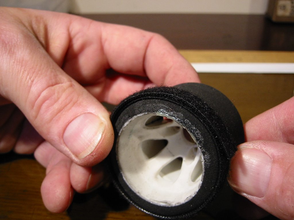
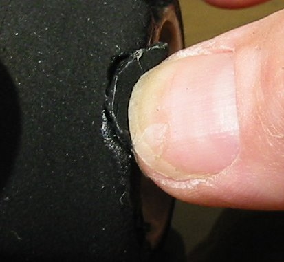
Try to peel back the tyre from the wheel on the outside edge using pressure with your finger or thumb against the side wall. If there are any gaps developing between the tyre and wheel (even small ones), you must repair these now. Failure to do this will result in further damage in this “peel” area and eventually whole bits of the unsupported foam rubber will be ripped away from the tyre resulting in the dreaded chunking.


Use the right Glue

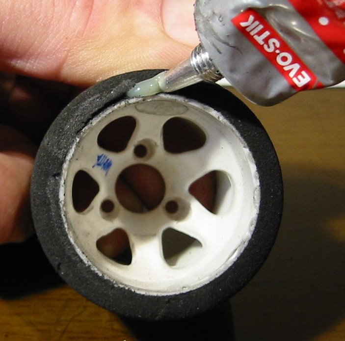
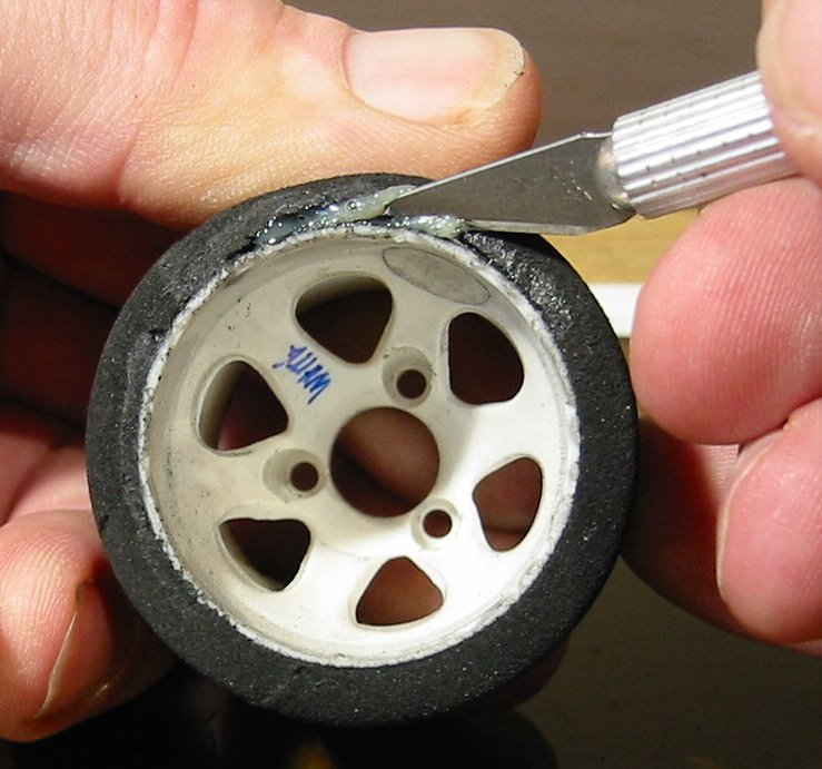
Squeeze some contact adhesive (I use Evostick) into the gap and then work it around with the end of a knife or miniature screw driver. Do not use superglue! With foam tyres we need glue that will flex with the tyre. If you use a super glue or cyano type adhesive you will create hard spots in the side wall and the tyre will rip around these spots again.

If you have made a large repair, it might be a good idea to apply some light pressure around the outside of the tyre while the glue sets. I use a strip of “Velcro” to do this but a rubber band will do just as well.


Leave the tyre for a good 30mins before you run it again.


Chunk Repair

Ok, when I explained this trick some of my racing friends; they simply did not believe me! So I have laid it out for you step by step. Unlike my most of my "improvement targets" in the A final , I do not get given tyres so this is all very important to my wallet!

To do this level of repair you are going to need a a tyre truer, a scapel knife, Evostick type contact adhesive and some nasty chunked rear tyres. I persnally find I have the latter in plentiful supply.

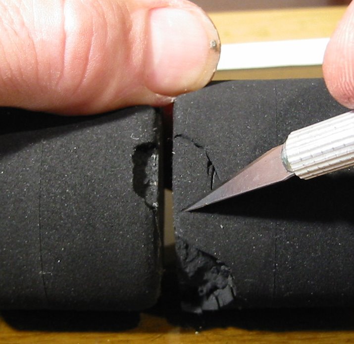
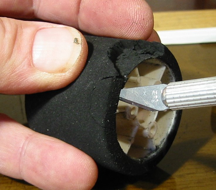
You will notice my patient tyre has two nasty chunks which I will repair at the same time (because I am that good nurse!). These chunks are quite small but to be honest, the smaller ones are harder to repair.


Step 1

Glue under any gaps between the damaged wheel and the damaged tyre. There may be small tears in the tyre that you are left with so you need to repair these with contact adhesive before we move on to addressing the bits of foam that are missing.

Step 2

Choose a donor tyre. This needs to be a scrap tyre of the same compound as the one under repair. It also needs to be slightly larger in diameter than the current patient also. This one donor will repair many patients!

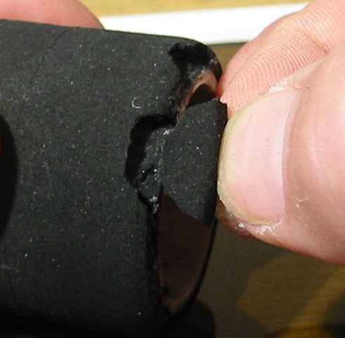
With a scalpel knife carve a chunk out of the donor tyre that is a similar shape but slightly oversized compared to the missing bit in the repair tyre. You will be surprised just how bad this match can be! Providing it is “sort of right”, we are going to be able to cram it on in there later! Try to match slants and features in the patient’s “hole” buy cutting these features in the donor chunk. Again do not worry too much but do make sure the donor piece is oversized.


Step 3


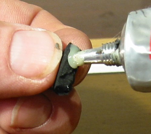
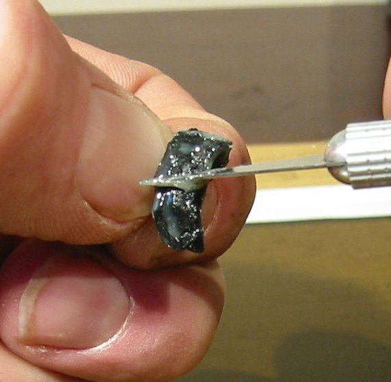
Apply Evostick contact adhesive to both the surfaces of the chunk hole in the patient tyre and the donor repair chunk. Make sure all surfaces that will finally come together when the chunk is pushed into place are well coated.

Do not over glue here. We are looking of a shiny glue finish on both parts. Wipe off excess glue. Do not bring the pieces together yet! We need to glue to dry off. This will take around 5-10 mins. Go make a cup of tea.

The idea of a contact adhesive is that the two parts are “tacky” dry before we bring them together.


Step 4

Now fix the repair piece into place. You only get one shot at this:

Hold the repair piece over the hole with slightly too much material than will fit, ready to be pushed into place. Start the contact point from the outside rim of the tyre working in. Really compress the repair piece into place. The contact adhesive (if dry enough) will grip it and hold it fast.

Now wait again. A good 30 mins is needed for the glue to go off. Go make a sandwich!


Step 5

A disclaimer, especially for my international friends some of which have a certain reputation for “compensation culture” attitudes….. Placing your hands near fast spinning objects is dangerous. Do not attempt this unless you are a consenting adult and you have assessed your own risks. I take no responsibility whatsoever!


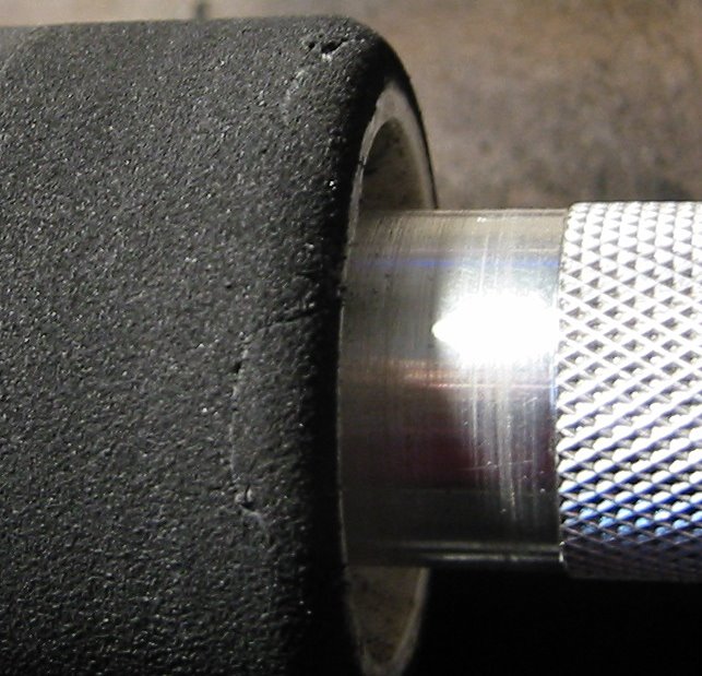
Place your tyre on your truer and wind the tool in over the repair area until it just starts to cut the oversized replacement chunks. Slowly grind these down until you are at the same diameter as the rest of the tyre. Take a final small cut on the whole tyre.


Now using glass paper, true the side walls very slowly cutting back the protruding repair chunks until the side wall is flat.

Finally round off the edge of the tyre with a small radius as normal.


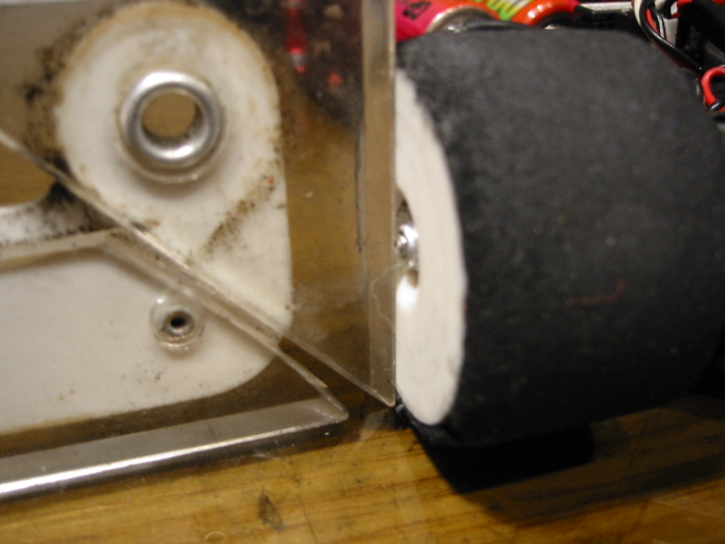
Congratulations! As the before and after images show. You just saved yourself the equivalent of £14.

Cheers

Mark Payne

Tuesday, December 20, 2005

CRC Carpet Knife 3.2R Total Tweak Guide

Total Tweak Guide for the CRC Carpet Knife 3.2R

Essential Reading and Prerequisites

In my previous posts on statically balancing the CRC Carpet Knife, setting good ride height and correctly building the Associated reactive castor front end, I was trying to lay the foundations for ending up with a totally tweak free car.

The following three articles are hence prerequisite procedures before moving on to the steps detailed below:


Please note that I only have experience of the CRC Carpet Knife 3.2R. Obviously the Associated front end is common to many cars but my total “system” assumes you have rear pivot ball and side spring type rear end.

Read these first:

http://markpayneblog.blogspot.com/2005/12/building-associated-l4-type-front-end.html

http://markpayneblog.blogspot.com/2005/12/crc-32r-chassis-setup-static-balance.html

http://markpayneblog.blogspot.com/2005/12/measuring-ride-height-on-crc-32r.html

The Coin Trick is Not Enough

Most people use the coin trick on the front tyres whereby you lift the front off the ground via the front center point and adjust rear tweak screws for a simultaneous coin drop. In fact I will end this article with the coin trick as a final tweak check BUT… the validity of the “coin trick” is dependant on other things being right first.

With the coin trick, what you are doing is setting the rear tweak screws to equate the downstops (limit of upward front suspension travel) of the front suspension. This is a factor of how accurate the front lower arms are and the ride height spacers included under them. Why would we set the tweak on the rear springs to fix a potential error in the front arms? The rear tweak should adjust the springs when the chassis is LOADED onto the springs all round, not unloaded at the front.

Don’t worry… if you don’t get this yet… we will go through the whole thing here.

Lets Start

I am assuming you have done the following checks (read the previous posts above):

A. You have a well built front end with all the slack just shimmed out of the king pins.

B. You have a fresh ground set of accurate and equal tyres on the car. The left and right tyres are exactly the same size measured with your calipers.

C. You have set the ride height to 4mm all round using the “five points” system.

Step 1

Remove the whole rear tweak bar assembly and damping tubes. We will be setting up the front end first. Load the car with a set of cells. You will notice that I tape cells into the car. I do not use the CRC “rubber band” cell retention as I believe this can tweak the car.

Now that the tweak bar is off, it is a good time to check the chassis pod is rotating freely. When a CRC car takes a crash, the centre pivot plate can be shifted out of line causing the rear pod action to bind. I now tend to check this every run at important meetings.

Video: Checking Pod Movement

If in doubt, loosen the two pivot plate screws and retighten them with the pod aligned with the main chassis. Recheck the pod action again.


Step 2

Spend some time and make sure the camber on the front wheels is set to 1 degree and is the same left and right. I use a protractor that I have had since my school days (its old!) but there are plenty of camber gauges on the market.


Step 3

Take the front wheels off.
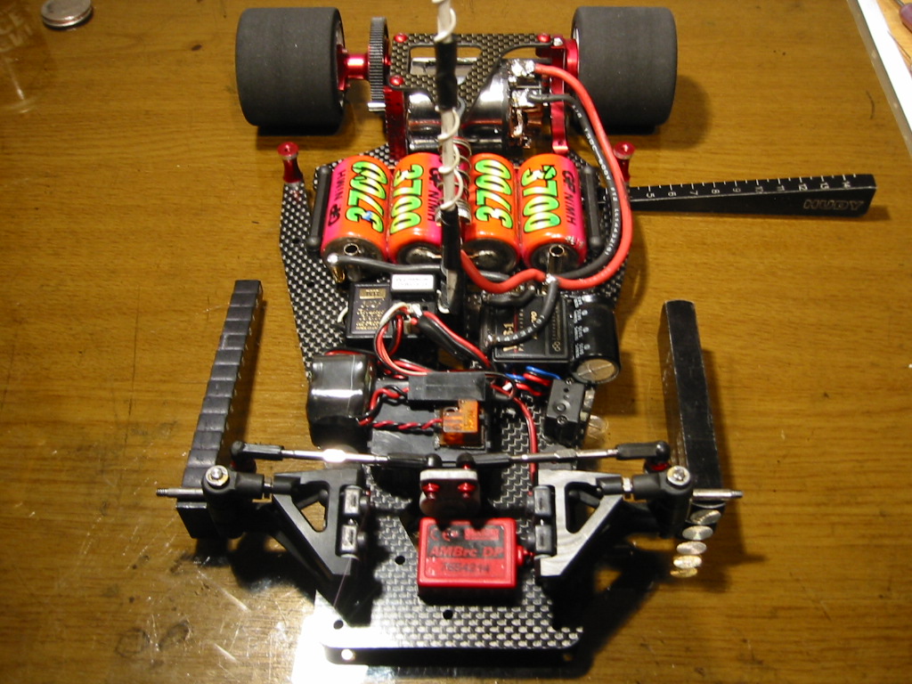
I put the chassis on 5mm blocks. Hudy make these http://www.hudy.net/xhudy/products/proddesc.php?prod_id=153&kategoria=64


Make sure the chassis itself is on the blocks and not any protruding screw heads, cells or cell tape. If the blocks are parallel to each other there should be no “rocking” evident. If the chassis rocks on the blocks then it is twisted. You will never tweak this car out with a twisted chassis.


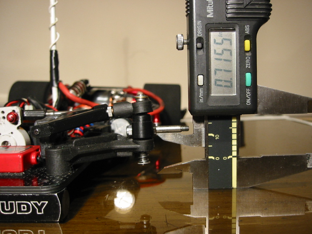
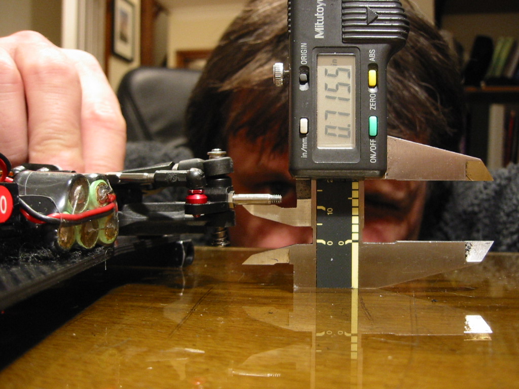
Now use your calipers as shown to make sure the front axles are at exactly the same height off the glass. If they are not I grind the front A arms until I have the a perfect match. If you have followed my previous front end instructions then there should be no issues here and this is just a sanity check. If the axles are not at the same height to within 0.25 mm (0.01 in) then you have a problem that you must address.

Step 4

Put the rear tyres on (fresh ground). The rear tweak bar and side dampers are still removed. The centre shock and spring is on as normal.

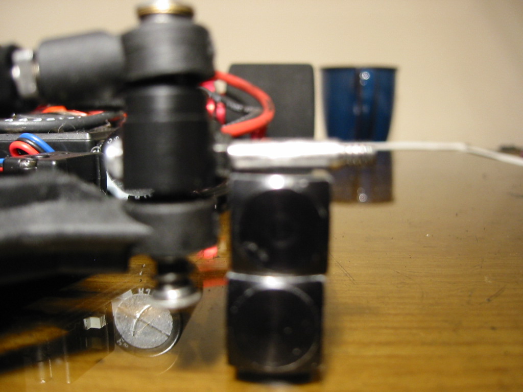
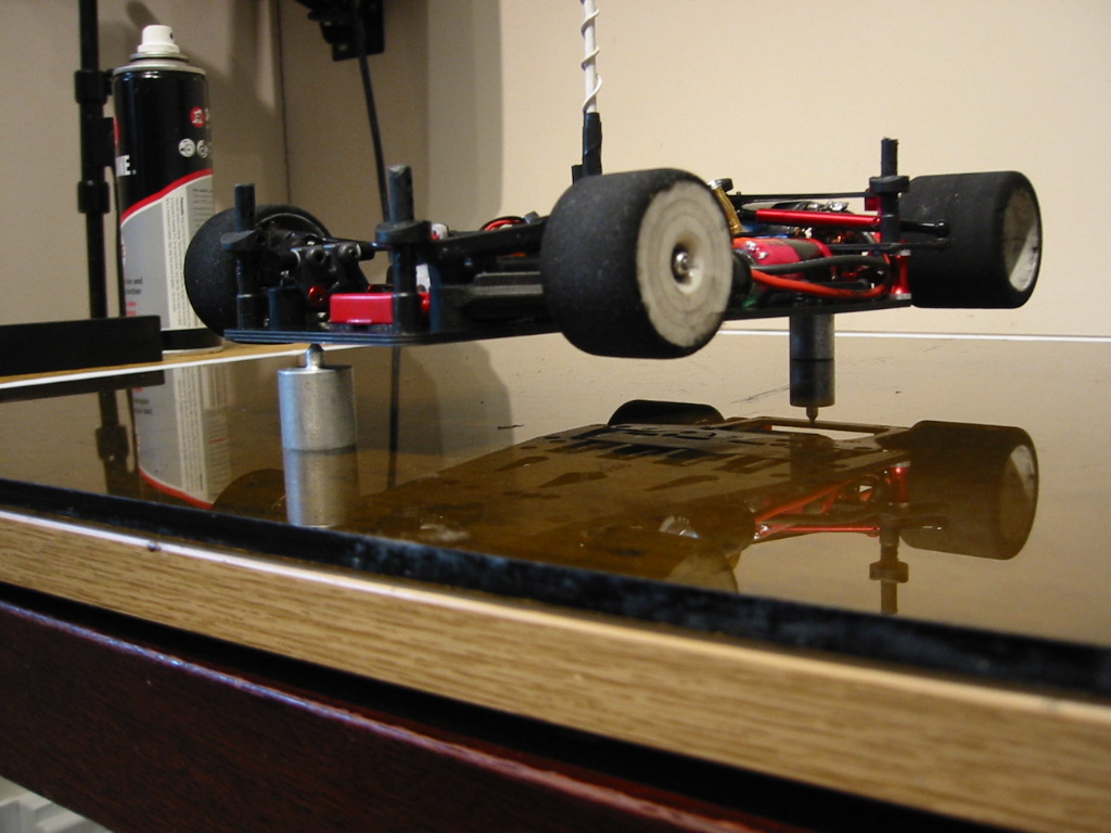
I now place 10mm blocks under the front axles (ok, I use whatever I have at hand to make an accurate 10mm block). The rear end cannot impose any tweak on the chassis as there are no side springs. Even if there is a slight error in the rear tyres, this cannot be transferred through to the front end. The lateral balance of the chassis is now purely a function of the front springs only. You statically balanced the chassis already right? (I do hope you have read the prerequisite steps ;-).


Something to be aware of … we balanced the chassis as a whole earlier but right now the front springs are subject to the full running weight of the car but the weight balance is being imposed by the front part of the chassis only.

I asked myself .. “ what if there is a balance error in the rear pod that we correct in the front (main) part of the chassis?” … Let me save you some time. I took the rear pod off and measured it’s balance complete with motor and pinion etc, it is crack on. An engineering thing that Calandra have got 100% right.

Step 5


Now with the chassis loaded onto the springs at the front, any left/right differences in loaded spring length will result in the chassis not being laterally parallel to the glass. This error will be maximized at the back of the main chassis near where the tweak mounting pods are attached; this is where I measure using a “wedge” type ride height gauge.


Add or remove one or two king pin shims until the left and right reads exactly the same. You will be taking a shim out on the high side or placing a shim in on the low side.

Assuming you (just) shimmed out the slack in the king pins earlier, if you now have to add or remove more than two shims on either side to get things right at the back… alarm bells should be ringing. Something else is wrong here. Go back and check the build of the front end (separate post) and the previous steps in this section.

I generally only accept the addition or removal of one shim on one side or the other at this point to level things up.

Step 6

Its time to put the tweak brace back onto the car. But before we do this I have some tedious details to discuss!

Motor Wire Warning

Be careful. The wires going to the motor can tweak the rear pod, resisting it’s free movement. To help with this I use 14 AWG wire, not the 12 AWG I have in my kit from 1/10th scale touring cars!

I take the wires under the tweak brace. If you go over the top they can catch on the body, again introducing tweak.

Which Side Spings?

I generally use the red side spring as a starting point. I go to the white spring (softer) for less direct steering. There are two main things I have learnt about adjusting these springs.


The first point is to make sure the spring sits on axis with the tweak screw and mounting. If it is off centre, you get unpredictable changes as the tweak screws are adjusted.

Now attach the tweak brace and I will come to the second point:

Start with the tweak screws wound right out (springs tight against the brace). Now wind down the same amount on both sides until the springs just touch the balls. I have read CRC setup notes where it has been recommended that this is how you should run the car. Ie. With the springs just resting on the balls when the chassis is flat. But…. My second main point is that I have found the car much more predictable if I load two full turns of spring tension beyond the “touch down” point.


Leave the side dampers off for now. The front end is still on the the 10mm blocks.

Now look from the rear and lift the rear pod off the ground using the centre point. I adjust the rear tweak screws to ensure both REAR wheels lift at the same time. If you are adjusting the tweak springs by more than ½ a turn on either side, alarm bells should be going off again. Go back and recheck everything because something is wrong.

Step 7

Now look from the front and sanity check the action of the front suspension. As you lift and release the suspension up and down using the centre hole at the front, you should see the same spring compression and expansion working equally on both sides.

Video: Comparing Left and Right Front Spring Action

Well done! You car is now corner weighted and applying balanced pressure left to right.

Step 8

Now comes the “coin trick”!

Why are we doing this?

To be honest, if you have carried out all the steps above, you don’t really need to do this. Remember your car is tweaked out evenly on the springs and the “coin trick” is going to lift the whole front suspension off the springs. Is this how the car drives? I think not. You already know the front axles lift off at the same height, because you checked this at Step 3.

However, assuming that you have laid the foundations by doing all of the above, the “coin trick” is the quickest way of re-tweaking the car to allow for the errors that creep into the tyre diameters after a run. No track imposes even left/right tire wear and we have to reset for this each run.

I swap the left and right tyres over each run to balance the wear rate up. After doing this I will re-tweak using the coin trick rather than do through the total “system” from scratch.

The Coin Trick

UK readers will want to find two 20p pieces or two £1 coins if you are feeling rich! As the CRC CK 3.2R is such a well engineered American car, I like to use $1 coins….. also this prevents me from spending my tweak tools at the tea bar on race day :-)

Attach the front wheels (fresh ground, the same size!) and place the car on your level flat surface.

Now place your money on the top of both front wheels, just slightly beyond the apex (by the same amount). Now lever the car up using the front centre hole s l o w l y.
The wheel that lifts first will drop the coin first. This is the high side.

Video: Coin drop on a car with bad tweak

Correct the high side (coin dropped first on the left here) by winding the tweak screw down on the opposite side (clockwise turn on the right in this case). Alternatively back off the tweak screw (anticlock) on the same side as the “early drop” coin. Adjust by no more than 1/8th of a turn at a time. If you are using more than ½ a turn either way then something is wrong or it is time to re-true your tyres.


Video : Coin Drop with good tweak

Conclusion

If you join me at this point then I congratulate you! You are as “sad” as I am :-)
… but I am confident that you car is going to go straight when you power up!

Happy racing!