Tuesday, August 07, 2007
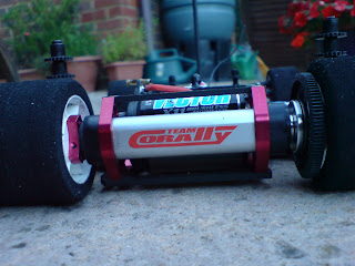
Corally Rear Wheel Bolts M2.5 !!!!

Corally SP12X Diff Nut Trick
The Corally diff is one of the best I have used with a great smooth and reliable action provided by the outer thrust race that comes as standard. I have a tip here that will solve or prevent the diff nut coming loose. Before we start be warned!!!!
Warning 1. The tiny thrust race balls are NOT captive within the spacer and its "game over" if these go on the carpet!
Warning 2. I am going to do stuff with superglue, fingers, carbon parts and tissue paper. We need to make sure that all 4 of these components are separate at the end of the process.
Step 1. Read Warning (1) above and strip your diff down. We want the shaft.
Step 2. Place a small drop of super glue on the threaded part of the shaft and then quickly and evenly wipe it into the thread with tissue paper, forming a smooth and thin (very thin) layer coating of super glue over the thread. Do not allow super glue to touch the non threaded parts of the shaft.


We are not looking to fill up the thread groves with glue here. The objective is to use the glue coating to slightly oversize the thread.
I used a standard viscous super glue off the DIY shop shelf. I would worry about the "Orion" type of watery thin cyano that is popular for mounting rubber tyres. Introduce a drop of this and it can capillary itself all over the the thread, the shaft, your car, your fingers and the work table! That's Warning (3).
Step 3. Wait Wait WAIT for the glue coating to fully dry before you try the nut on the thread. You really do not want to superglue the nut to the shaft here! Try the nut on the shaft, it will now feel tighter. Ideally you want it to fell tight enough to be difficult to turn using your fingers alone but easy with your diff spanner. I repeated step 2 a couple of times until my nut was "locky" enough.
Step 4. You may now find the spur gear bearing will not pass over the thread as you have slightly increased the outer diameter with the super glue coating. This is easy to rectify. Just rotate the shaft by hand while holding the thread with some fine abrasive paper wrapped around it. This will remove some of the super glue and reduce the outer diameter of the shaft whilst keeping the coating in the thread groves.
Job done!
A final tip. I alway loosen the diff off after the end of a meeting. This prevents the O ring being over squashed and distorted.
Cheers
Mark
Sunday, August 05, 2007
SP12X T-Bar Setup
Corally SP12X : Front End


Sunday, July 29, 2007
Mark joins Corally Team. SP12X

I had to try something different! Since winning the 2005/2006 F2 19T and Modified Championships in the UK, my first year (2006/2007) as an F1 driver was not great to be honest. I like to improve and feel I am making progress but had hit a brick wall. I had a bad Worlds followed by a bad Euros and started to loose confidence.
Going Backwards
I seemed to be going backwards with the CRC. I had the 3.2R with the ABP chassis running really well but the move to GenX was not working for me. In fact I had my best results last year with a CRC T-Fource. There are many many top drivers doing well with the GenX but I think we have a particular problem in the UK with lower traction (compared to the US) which suit’s a T Bar car over a link car.
The Final Straw
The final straw was at the first of the Chesterfield summer events where I left the meeting in an internal frustrated temper before the finals. I have never left an RC race even when having a bad day…..
Watching the Competition
Remember that I am only an ok_to_good driver and I think a lot of the problems ended up in my head. Either way … it was time for a change. I had been watching Roger Manwaring in the UK put the Corally SP12X down and instantly appear to be smooth and precise. I must admit that I am a little influenced by David Spashett also! With other upper mid-field F1 drivers including Rambo (Michael Ramsbottom) and Mark Jewitt doing well (and getting away from me) and rising stars like Chris Kerswell and Matt White making A finals, I decided on the Corally (what a terrible sheep I am!)

So here it is…. I will be updating the 12th blog with more Corally specifics as I learn them.
Many thanks to Pete Winton, Roger Manwaring and David Spashett who have got me hitting the ground running. Two meetings later and I have this huge smile on my face once again.
Mark
Saturday, February 03, 2007
CRC GenX Pro Strut Front End. Review and Building Tips
CRC Prostrut Front End

This has to the most radical development introduced on the GenX car. CRC have moved away from taking the Associated OEM front end from the L4 and created a front suspension system with a similar geometry albeit with a many new and unique features.
New Prostrut on the left with the Associated (with CRC Parts!) on the right.
The Prostrut system is totally compatible with the mounting holes of the Associated suspension allowing many (most!) drivers to take advantage of this new development.
New Features
1. The kingpins are threaded at the steering block end, allowing the adjustment of kingpin spring preload without the use of shims.
2. The steering arm pivots the king pin in a ball joint pressed into the lower A arm. This is similar to the Associated design but the top of the steering block terminates in a new pillow ball coupling (rather like a small version of the original Xray T1 touring car).
3. Both the top and bottom steering arm joints can be adjusted for wear and "slop".
4. Four castor angle options are available (3 on the Associated) by configuring the three Teflon spacers. These spacers can be moved easily without having to rethread the inner pivot pin. The castor block has a split design that allows this feature.
5. Reactive castor blocks (0, 5 and 10 degree, ala Associated) can be changed without removing the front suspension from the chassis.
6. The front axle diameter is increased to 3/16th inch, this requires different front wheel bearings but is almost impossible to bend.
Associated to CRC Pro Strut Geometry Comparison
Track Width
The picture shows a Pro Strut lower arm bolted to an Associated arm. The objective here is to show that the lower pivot ball location is almost identical. In fact the CRC pivot ball is 0.5mm closer inboard. This can be seen by the slight angle that a pin running through both pivots balls creates.

You may think that this would result in the front track width being 1mm shorter overall with the Prostrut but this is not the case. The CRC steering block places the inner wheel bearing surface 0.4mm further outboard (on each side). The photo below shows the Associated on the left and new CRC block on the right. The result is that although the kingpins are approx 1mm closer together on the Prostrut, the overall front wheel track width will be the same as the Associated setup.

Reactive Castor
The 0 degree, 5 degree and 10 degree reactive castor blocks on the Prostrut mimic the Associated geometry and place the inner top pivot pin at the same relative heights front and back. However, and this is a big difference, the inner upper link pin is much further outboard on the Pro Strut, lying directly over the chassis mounting hole centres. This makes the CRC upper suspension arm shorter by about 5mm on the (37mm for the Associated and 35mm for the Prostrut).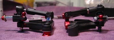
Short Arm
The shorter CRC top arm connects inner and outer pivot points at the same relative heights when compared to the Associated. This means that the top arm is more angled on the CRC (as well as being shorter).
The shorter CRC top arm should result in more camber change as the suspension compresses, as does the increased arm angle. The increased arm angle also lifts the front roll centre higher.
To be honest, I am unsure of the overall effect here. Camber change can be argued to increase grip (at the front) where the raising of the front RC decreases it! I have shown you the difference. Test it and see how it feels!
Castor Options
The GenX manual suggests to start with all Teflon washers forward (minimum castor). I have looked at this with the 0, 5 and 10 degree reactive blocks and the resultant castor angles are as follows (measurements taken with no compression):
All three shims forward ... -3 degrees (the king pin is going FORWARD!!!)
Two forward, one back ... 0 degree castor
One forward, two back ... 3-degree castor
All three shims back... 6-degree castor.
I would normally run the 3 or 6-degree options. To be honest I see no sense in the forward leaning king pin. You have been warned!
The three Associated options (no compression) would be 2,4 or 6 degrees depending on the shim positions.
Springs
The CRC springs are shorter than the Associated ones by around 0.5mm (0.020"). You could run the Associated springs but you will run into problems here if you are not running CRC hi-roller wheels as the extra 0.5mm length adjusted into the king pin fouls the inside of a "standard" front wheel.
The larger CRC hi-roller wheel allows you to run whatever spring you like, CRC or Associated. Personally I run the CRC springs and have settled on the CRC 0.50mm spring which is slightly harder than and Associated 0.020". Note the CRC springs end up being a little harder for the same metal diameter as CRC spring coil density is less (less turns per mm of spring length).
Building The Pro Strut
These tips are in addition to the Gen X Manual.
1. Ident Your Castor Blocks
The reactive blocks are not marked as to 0 degree, 5 degree or 10 degree. As shown, I paint a little white Tipex blob and write on the block angle with a thin marker pen. Hopefully this will help prevent ending up with different blocks on each side (been there, done that).
2. Hand Finishing the Upper "A" Arm
The secret of reliable handling lies in free movement of the front end. It must not stick or bind. I use a 2mm drill (by hand) to ream out the upper arm pivot holes. Work the drill by hand until the pin rotates freely.
3. Finishing the Castor Blocks 
I find the split castor block slightly oversized, again causing the upper suspension arm to bind. Assemble the top part of the molding and screw it down. Grind the length down slightly rubbing on abrasive paper. Do this until the upper arm does not bind.
4. Upper "A" Arm Binding Check
When you assemble the upper arm it should drop under its own weight. This is a good test to make sure there is minimal friction here. If it "stays where you put it" its time to revisit step 2 or 3.
5. Teflon Balls
CRC provide a delrin lower pivot ball in the kit. It's fine but I prefer to use the Teflon coated metal ball ( http://rc4less.safeshopper.com/22/389.htm?692 ) that I also used in the Associated front end. Now here lies a problem: 
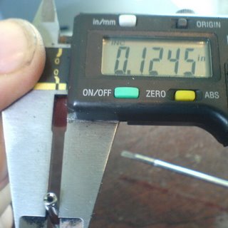
A standard Associated 1/8th inch (0.1250" in theory) king pin measures 0.1240" diameter giving 1 thou of running clearance, the CRC threaded king pin is very accurately ground to exactly 0.1245" resulting in only 0.5 thou of clearance.
The result is that the CRC king pin is perfect in the CRC delrin ball but it binds in the part I want to use! My solution is to polish down the CRC king pin diameter by popping it into my dremel and rotating it in 240grade abrasive paper (lubricate with spit!) followed by 1500 grade finishing with wire wool to put the polish back.
6. Upper Pillow Ball

When assembling the pillow ball upper joint, do not over tighten it. There is no point in doing this. There is nothing wrong with a little suspension slop. Its really nice with the CRC Prostrut to have the adjustment to take out wear but if you overdo it, your suspension will bind up on the track.The GenX manual suggests tightening it up and then working the ball joint by hand to break in the parts. Do this but then remember to slacken the screw out slightly to free up the ball joint. Check this after your first few meetings and readjust once things have worn in.
7. Lower Clamping Screw
The same is true for the clamping screw that takes out the play in the lower A arm ball joint. Do not over tighten this. The manual suggests that there should be "just a little drag" resisting the movement of the lower ball. Sorry but I disagree here, I would suggest you set this for "just a little play". If the lower ball is not free to move it puts a binding load on the movement of the kingpin. Again check after a few meetings and readjust allowing for break-in.
8. Binding Check
Assemble the whole front end as per the manual but don't lock the king pin in place (leave the small set screw loose for now) and don't put the spring or e-clip in place. This will be your final check for binding. The king pin should move freely up and down through the lower ball joint. If you push the king pin through the ball (as if compressing the spring that is absent (!)), the whole steering block/upper arm assembly should drop back into place under its own natural weight, without binding or restriction.
9. Adjusting the Kingpins
Once the suspension is free, its time to put on the springs and e-clips. Using a 0.050" driver screw the kingpin in until the spring just touches the e-clip and the play is taken out of the suspension. Remember this is with no load on the spring as the Prostrut suspension is still in your hands and not on the car!

Compress the spring a few times to "pre shrink" any shortening that often occurs when the springs bed in. Readjust to take out the play.Now it comes to tighten the grub screws that will hold the kingpin in place and prevent it from rotating. A word of warning here:
The original grub screws were steel, threaded into the alloy axle piece and made tight onto the screw thread of the king pin. The risk here is that if you over tighten the grub screws, you damage the threads in the axle block on the kingpin itself.I think CRC changed the grub screw for brass in the second run of kits and these are available as a part here:
http://www.teamcrc.com/crc/modules.php?name=Shopping_Cart&file=product&c_op=viewprod&prodID=7718936
10. Threading the Lower "A" Arms
I have seen reports of people smashing lower A arms in crashes not deemed worthy of breakage. I run unlimited modified class and I have launched the car into various obstacles without problems.
Bottom line is that I have a pit box full of broken Associated A arms and I am sure there will be some CRC stock to add soon! Keep spares. If this part does not break in a bad crash it will rip itself out of your carbon chassis, I know what I prefer.
However, what does worry me is reports of people splitting the arms around the mounting screw holes as they cut the threads in for the first time. The GenX kit supplies a stainless steel screw to do this and you should use it, but here is a tip:

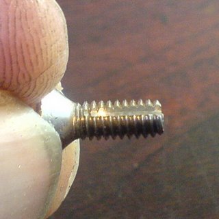
We are going to use a cutting wheel on a dremil to convert the GenX kit screw into a tapping bit. Simply cut two slots in the thread as shown on opposite sides (180 degrees apart). You could also do this with a needle file and some patience.
Now when you use this tool it will cut a thread rather than "force" a thread. This will reduce the risk of damaging the part while cutting the thread the first time and it will go onto the car without the holes being held in expansion stress.
11. Grinding the carbon ride height spacer
I have stopped using the pretty red ride height collars. Your mileage may vary but I have managed to crush/deform two of them in a bad accident leading to errors in ride height accuracy (readers of my stuff will know I am very anal about these details!).
I would prefer to see a little more alloy in theses but in the meantime: CRC make a must have alternative lowered carbon spacer:
http://www.teamcrc.com/crc/modules.php?name=Shopping_Cart&file=product&c_op=viewprod&prodID=7718937
These spacers will allow you to run smaller front tyres and also are recognised as adding strength to the front end. The picture shows the grinding I do on these before using. Do not use them without such a modification, as they will tweak the front end by putting pressure on the heads of the screws that secure the castor blocks.
12. Attaching the Prostrut
The final step is to attach the front end to the chassis. As with the Associated front end it is important to not over tighten the 8-32 screw otherwise you will deform the alignment of the lower A arms leading to left/right ride height differences. You also risk deforming the chassis carbon around the countersunk holes making accurate seating of the arms more difficult.The screws need to be just tight to hold the suspension without movement and no more. I like the Lunsford titanium screws available here:


