Chassis Balance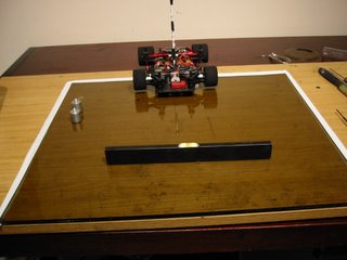
Tweaking out the chassis for predictable handling on a 1/12th car is going to be dependant on a good static balance from left to right as a starting point.
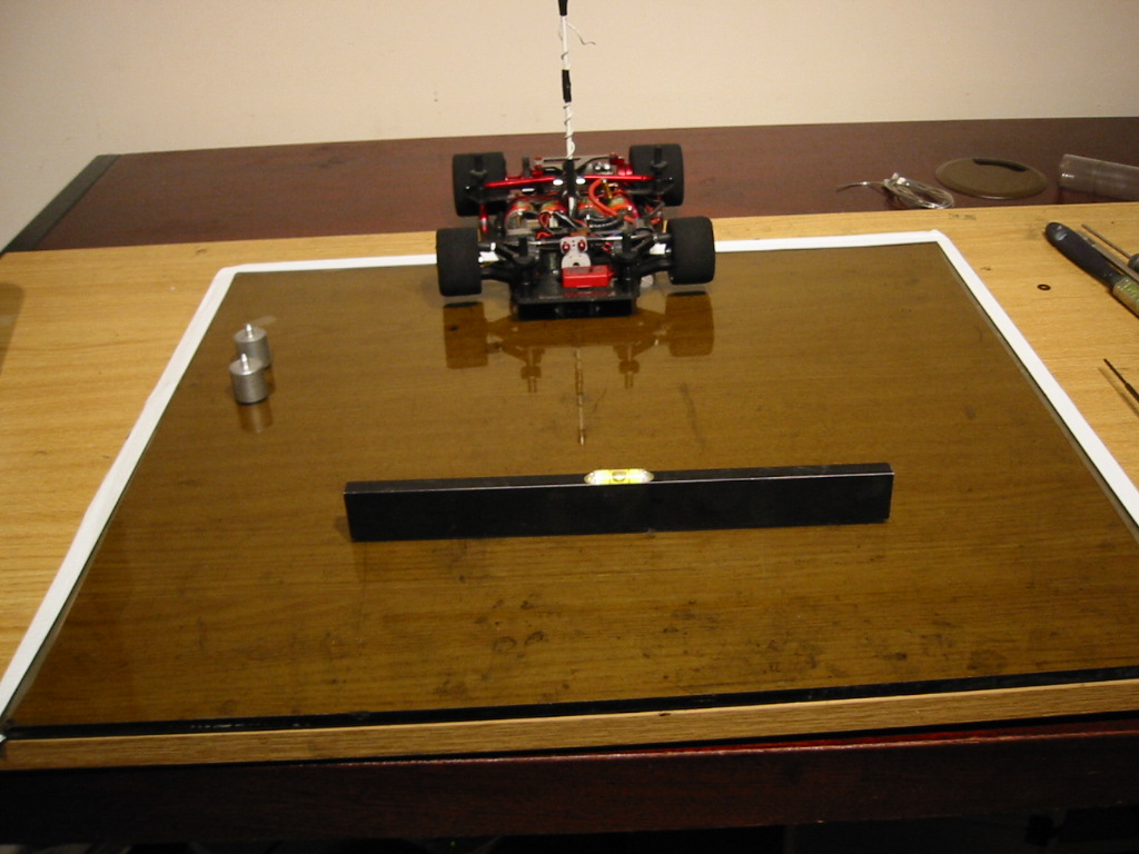
Start with a flat surface which is level on your workbench. I use a piece of safety glass (pop down to your local glazing company for an off cut). Level the glass out with a spirit level.

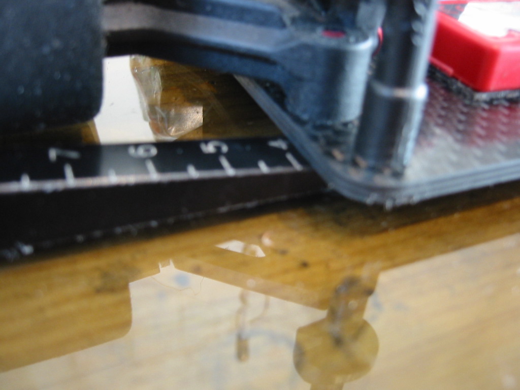
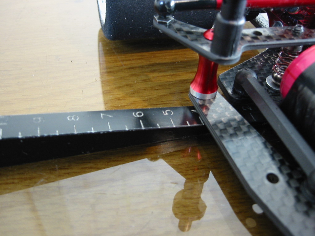
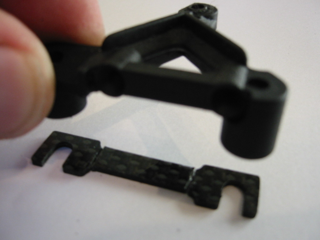
The chassis will need indentations or small holes at the front and back on the centre line of the car to allow the correct location of balancing pins. The rear hole needs to be located on the back cord of the rear pod. I cannot remember if the CRC rear bottom plate has this hole and the front definitely does not.
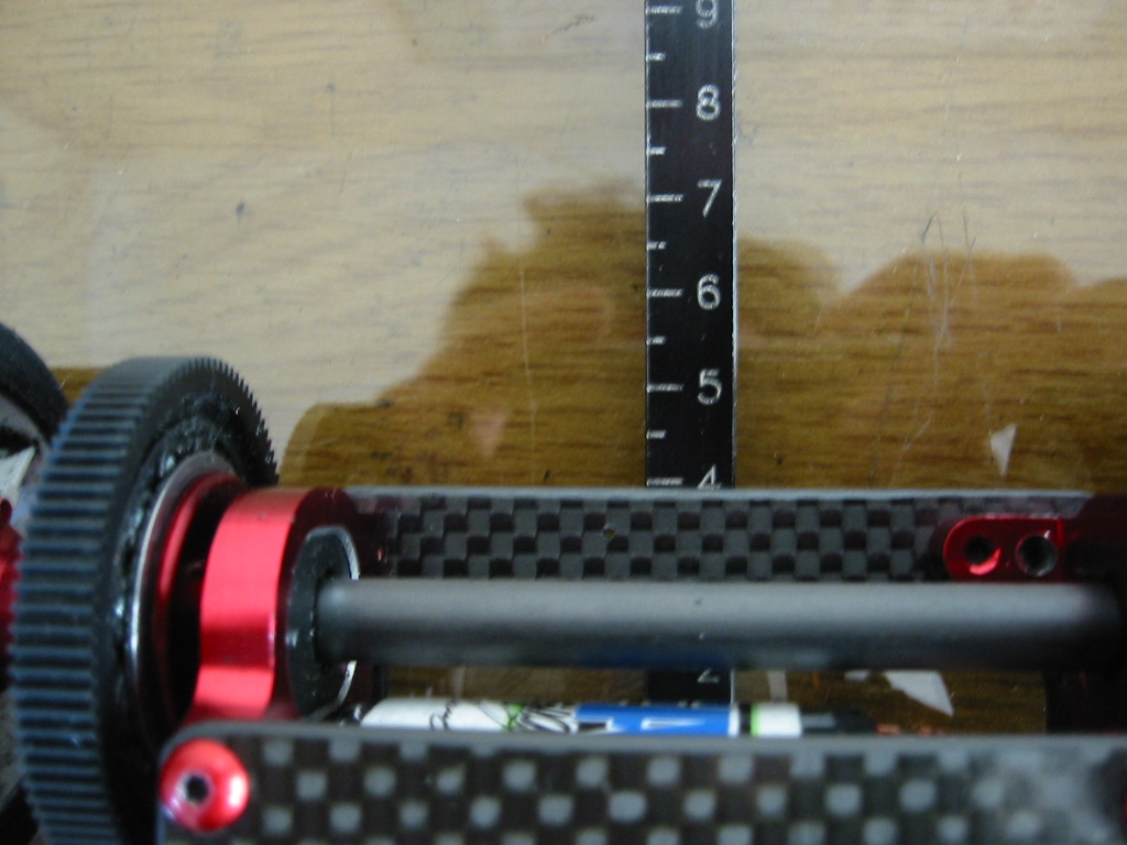
Use a set of calipers referenced off the inner edge of the rear wheels to find the centre line of the rear pod, the whole pod is off centre so this is the only reference that makes sense. The centre line at the front is easier to scribe from the edges of the chassis.
Now comes the balancing bit...
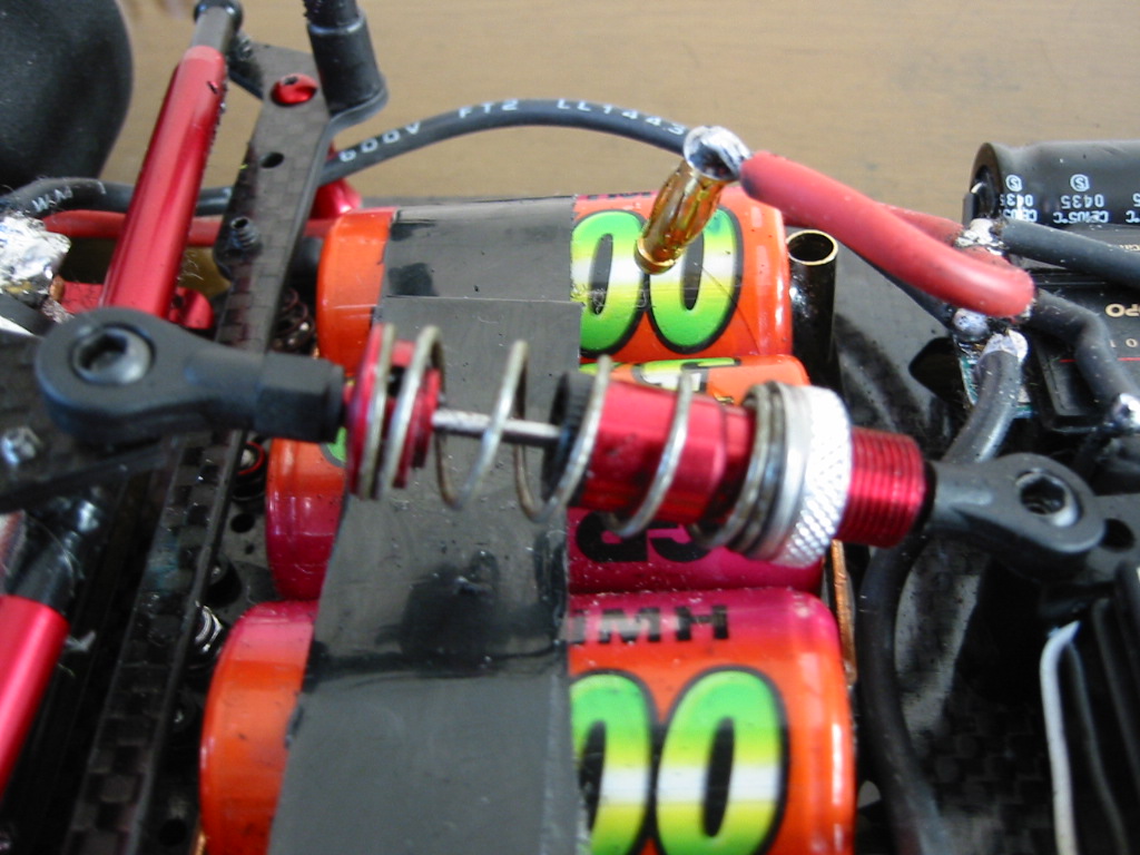
Set the car up with all your gear, wheels/tyres on and set for correct ride height and rear pod droop (more on this later). Batteries in, pinion on and wiring all plugged up ready to go. Just don’t stick any of your electronics in yet.
The variable items that can be moved around will be the speedo, radio receiver, RX battery pack (if you use one) and Personal Transponder (PT). I place the PT last to fine tune the chassis balance by moving it between the steering blocks at the front.
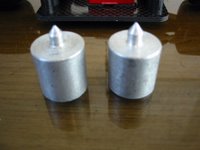
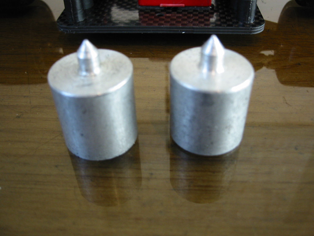
I have made a pair of alloy balancing pins which locate into the holes made earlier in this discussion. HUDY make these things if you have need
http://www.hudy.net/xhudy/products/proddesc.php?prod_id=173&kategoria=64
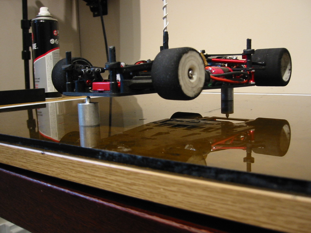
Place the car on the pins and use a spirit level over the back tyres to locate the car parallel to your flat surface. Now when you remove the sprit level, the car will obviously fall over on the heavy side. You can now move your electronics around until the car balances perfect

ly on the pins.
Finally locate all your gear and stick it down. You are now ready to move on the next part of the chassis setup.
Brushless Update Nov 2006Here we have a problem, the approach above is valid for your brushed modified and 19T motors. This is becuase the rear motor pod is almost perfectly balanced with "traditional" motors. However...... brushless motors carry a weight unbalance where the pinion side is light compared to the connection side.
You may be tempted to try and correct this by shifting weight around in the font part of the chassis. This is an error in my opinion. The front part of the chassis should be statically balanced independant of the rear pod.
A full discussion of this can be found here:
http://www.rcracechat.com/vb/showthread.php?t=23696 ... some of my collegues are arguing with me here which is generally a lost cause ;-) so I will reprint the main points below:
*************
Set the scene: If you take your rear pod off your car and keep it complete with rear axle, wheels, average 10 turn modified motor and pinion and then pop it in balancing posts.... it will balance (left to righ lateral balance), pretty much spot on. So.... join the car up again and put the whole thing on the balancing posts and balance it out by the arrangement of the electrics and you have a tricked out car. I have already documented this all in the blog. Now the brushless: Ooooh ... interesting (come on, if you are down this far you are interested) again my brushless post on 12thrc tell us that my LRP brushless setup is about 30g heavier than the brushed. This is not news but the balance of the motor is different. There is a lot more weight at the (I was about to say commutator end!) ... at the sensor wire/connection end, away from the pinion. This unbalances the pod. As a result, if you then correct this in the front part of the car you end up shifting weight over to the pinion side of the car. In fact, I can only achieve overall balance by adding a 5 cell RX pack right over on the pinion side. So.... I am left thinking... is this the right thing to do? When this lot sits down on the deck the front chassis is applying a slight twisting force through the tweak springs to corner weight the rear tyres. So I have decided to remove the pack which balances the front part the the chassis (take off the tweak brace and you can pivot the chassis around your front end lifting point and the rear pivot ball) but leave the car overall with an inbalance due to the pod.I think the real fix would be a modified pod with the bulkheads moved over to the pinion side (yes resulting in a shorter diff side axle offset and a longer offset on the other side). However this is really NOT an easy win.Also in Worlds brushless trim without my pack the car is at 885g (that is with my 3700s in!). The limit is 865g. If I were to run the pack and the 4300's I am going to be well over 900g.